A very simple yet interesting Chasing LED arrow car tun signal indicator circuit is discussed in this article.
The circuit uses just a single 10 stage Johnson's decade counter IC 4017 and an UJT for executing a very interesting two pattern LED light chasing on the connected LEDs, which produce an impression of creating an arrow in a given direction. The following GIF image tells us how the pattern might look when its installed across the car turn signal slots.

As may be seen in the pattern, the LEDs are grouped in different numbers across the channels, and once illuminated these light up to produce a bar graph kind of chasing and single channel chasing effect alternately.
The circuit which is responsible for generating the above chasing LED arrow in a car tun signal indicator , can be witnessed below:
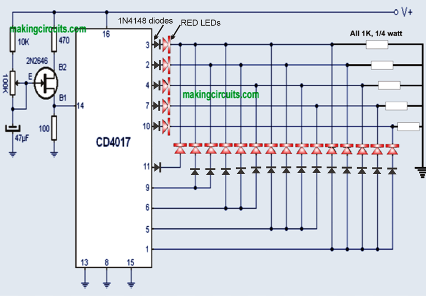
The idea looks pretty simple, a single IC 4017 is configured for carrying out the chasing LED in an altyernately bar graph and dot mode through a special smart arrangement of its pinouts across the connected LED series parallel channels.
The speed at which the chasing eect on the LEDs is supposed to happen is determined by the flashing rate of the UJT device at pin#14 of the IC4017.
The flashing or oscillating rate on the UJT can be fixed by adjusting the associated 100 pot or a preset or/and the 47uF capacitor.
This in turn determines how fast or how slow the LED chasing on the LEDs can be achieved.
Once installed this car LED chasing arrow turn signal indicator will instantly start producing the expected light show and produce the required turn signal indication in a much enhanced compared to the conventional single bulb flashing indicators
Yavuz says
Hello there. I wonder when you will share the simulated circuit of the circuit, I am planning to make the circuit, but I read the comments and it seems to be a problematic circuit. I would be very happy if you share the final version of the circuit. I request you to send me the final version of the circuit by e-mail. [email protected]
regard
admin says
Hi, the circuit is not problematic at all, it will definitely work….just make sure to build the UJT circuit correctly.
jason says
HI, not sure I completely understand the circuit, where do you position the LEDs? Is it after each diode?
admin says
there are no diodes, the LEDs (red symbols) are connected directly with the IC 4017 pinouts, just as indicated in the diagram.
jason says
ok thanks , the top of the diagram says 20 1n4148 so I put that in my schematic.
admin says
that looks like a printing mistake, I will update the finalized diagram shortly, please bear with me.
plasma says
Hi sorry, me again with more questions. I’ve now built this circuit but I couldn’t get it to output anything with the circuit exactly as it is above. I discovered however that the circuit diagram is possibly missing 5 earth connections from the points where the LED Cathodes meet each other? I connected these to earth with a 470 Ohm Resistor and the circuit now functions. However its doesn’t function as expected I’ve double checked all my connections. At no point are all LED’s on like in the GIF and in the description. Difficult to explain as the LED’s aren’t numbered but I get the block of 5, 4, 3, 2, 1 then the 5 individual ones come on one at a time, then it starts again with the block of 5 LED’s. Currently triple checking my wiring, but can you think of any reason it might not work?
admin says
yes you are right, that was very silly of me….I’ll correct the circuit diagram soon by adding the resistors.
sorry this diagram was picked from another site and I am having difficulty in simulating the GIF image with the actual functioning of the 4017 output…
plasma says
The Arrow GIF at the top show 25 LED’s but the circuit only shows 20? I guess you could offset the first one and place it in between the others then drop one from each of the rows. Just seems a little odd to give a visualisation that doesn’t tie up with the example circuit.
Plasma
admin says
Thank you Plasma, that’s a good suggestion I am sure the other readers will note this and change the design accordingly in their models.