• Skip to main content
  • Skip to primary sidebar

Making Easy Circuits

Learn and build electronic circuits

You are here: Home / Power supply / Simple Dual Power Supply Circuit Without Center Tap

Simple Dual Power Supply Circuit Without Center Tap

Last Updated on July 2, 2020 by Admin 2 Comments

The article explains how to make a simple dual power supply circuit without using a center tap transformer rather any ordinary two wire transformer.

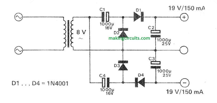
This circuit is of interest not merely  because it uses a bell transformer  with a single secondary winding to  provide symmetrical voltages for  low-current applications but also  because the final output voltages  are greater than the normal bell  transformer (220 V/8 V) output. In  fact the final output can be as much  as twice this value.

This multiplication  is achieved using two voltage doublers  each consisting of two diodes and  two capacitors, connected head to  tail.

Each diode/capacitor couple  takes every alternate half cycle of  the sinusoidal voltage such that the  output voltage U is (theoretically)  equal to 2V2 Ueff where Ueff is  the effective output voltage of the  transformer.

A current of 150 . . . 200 mA and  1 V of ripple can be expected using  the capacitor values shown here. ln  order to increase this current without  a similar increase in ripple the values  of the capacitors may be made  greater but C1 must be approximately the same as C2, and C3 about  the same as C4.

To get a stable symmetrical output  of 15 V two voltage regulators, a  7815 and a 7915, should be used.  This enhanced simple dual power supply circuit will then allow any two wire transformer to be used for any small circuits  with operational amplifiers requiring  a symmetrical supply of 14 or 15 V  and a current of 0.1 .. . 0.2 A.

simple dual power supply circuit

Simple Dual Power Supply Circuit

This simple dual power supply circuit is designed with a affordable and easy technique of acquiring a split power supply (for op amps etc.), employing the quasi complementary output stage of the famous LM380 audio power IC.

fig1 5

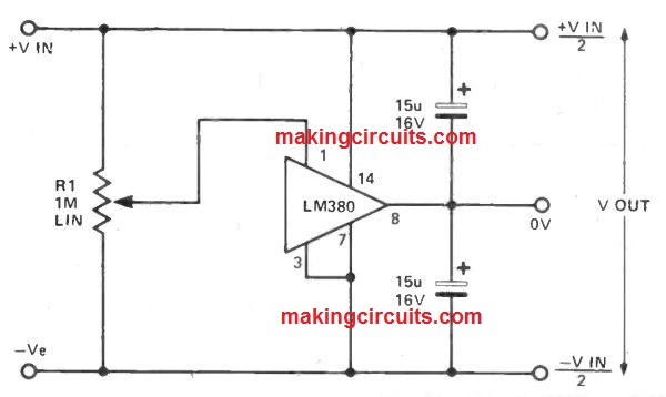
The IC has an in-built biasing so that without any input the output is placed mid way relating to the supply lines.

R1, which needs to be at first fixed at mid travel, is utilized to nullify any sort of asymmetry within the output.

Vout regulation is dependent on the circuit connecting the LM380, however the positive and negative outputs will track correctly despite of input regulation and uneven loads.

The free air dissipation is a slight above 1 watt, and thus excess cooling could be needed.

The simple dual power supply circuit device is completely secured and can get into over temperature shut down if its rated dissipation is surpassed, current restricting arises if the output current is higher than 1A3.

The input voltage must not go beyond 20 V.

You'll also like:

  • 1.  LM317 High-Current Bench Power Supply
  • 2.  1w, 4w, 6w, 10w, 12w LED Driver Circuit SMPS
  • 3.  Make this Soft-Start Power Supply for Amplifier Loudspeakers
  • 4.  Switching Lights ON/OFF from Different Locations
  • 5.  Ten Channel Touch Switch Circuit
  • 6.  High Current Voltage Regulator Circuit

About Admin

Hey friends, Thanks a bunch for stopping by this site! I am an engineer with a Bachelor of Engineering in Electronics and Telecommunication. One of my passions is gathering information from all sorts of electronics books and tutorials. I then take that information and compile it into a language that is super easy to understand. My goal is to make those complex electronics circuit concepts and technical terms much more accessible for all the new and budding electronics engineers out there. I can also design customized circuit diagrams as required by the users.
If you have any questions related to this field, please do not hesitate to drop a comment! I am always here and ready to help you out with any queries you might have. I cannot wait to hear from you!

Reader Interactions

Comments

  1. Thomas F. Lange says

    May 24, 2022 at 3:54 am

    If doubling the voltage is not desired (or even problematic), I believe one could use two bridge rectifiers “back to back”- one with the (-) to common, and the other with the + to common, taking + and (-) voltage outputs.

    Reply
    • admin says

      May 31, 2022 at 11:12 am

      thanks for the feedback, appreciate it

      Reply

Leave a Reply Cancel reply

Your email address will not be published. Required fields are marked *

Primary Sidebar

Categories

  • 3 Phase (4)
  • 8051 Microcontroller (1)
  • Arduino (11)
  • Audio and Amplifier (102)
  • Automation (8)
  • Battery Chargers (64)
  • Bicycle Projects (4)
  • Car and Motorcycle Projects (39)
  • Datasheets (10)
  • DIY Projects (5)
  • Electrical (15)
  • Free Energy (6)
  • Games Projects (2)
  • High Voltage (14)
  • Hobby Projects (30)
  • Household Circuits (2)
  • IC 555 Circuits (5)
  • Ignition Circuits (2)
  • Indicators (50)
  • Infrared (6)
  • Inverter Circuits (29)
  • Lights and Lamps (97)
  • Medical (8)
  • Meter and Tester Circuits (38)
  • Motor Driver (17)
  • New Circuits (56)
  • Oscillators (30)
  • Pets and Pests (5)
  • Power supply (80)
  • Protection Circuits (25)
  • PWM (9)
  • Remote Control (20)
  • Security and Alarm Circuit (48)
  • Sensors and Detectors (66)
  • Signal Processor (23)
  • Solar Controller Circuits (62)
  • SSR (3)
  • Temperature Controller (20)
  • Timer (25)
  • Transformerless (7)
  • Transmitters (12)
  • Tutorials (45)
  • UPS (2)
  • Voltage Regulators (57)
  • Water Sensor and Controller (29)
  • Home
  • Privacy Policy
  • Contact
  • Disclaimer
  • Copyright

© 2025 · Making Easy Circuits