• Skip to main content
  • Skip to primary sidebar

Making Easy Circuits

Learn and build electronic circuits

You are here: Home / Car and Motorcycle Projects / How to make a Car Interior Light Fader Circuit

How to make a Car Interior Light Fader Circuit

Last Updated on February 17, 2018 by Admin Leave a Comment

The submit clarifies a very simple circuit widely available for developing a slow fading light impact at any time it's shut OFF. The application might possibly be generally applied in car interior lights.

Nearly all of the advanced cars are designed with circuitry which switches on the Car's room lamp when a door is opened and switches off the lamp in fading way when the door is closed.

Right here a very simple circuit is introduced which may be fitted in old cars having no major changes to acquire the same consequence.

Before we realize the information of the circuit, it is advisable to figure out the wiring of a Car's interior lamp and how the door switches are functioned.

car2Binterior2Blamp


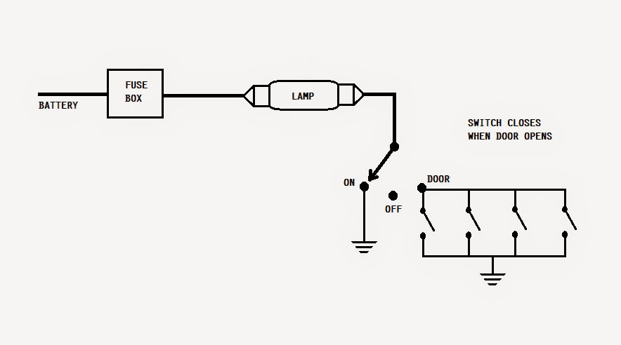
The lamp is hooked up to the battery's positive by way of a fuse. The other end of the lamp is linked to a single-pole-3-throw switch.

When finally this switch is situated at ON, the other end of the lamp gets plugged into ground i.e. the negative terminal of the battery for this reason, the lamp gets activated.

In OFF place, the lamp continues to be shut off from the ground. In DOOR position, the lamp gets joined to the ground by means of door switches (in parallel). When a door is opened, the respective door switch is closed.


car2Blight2Bfader


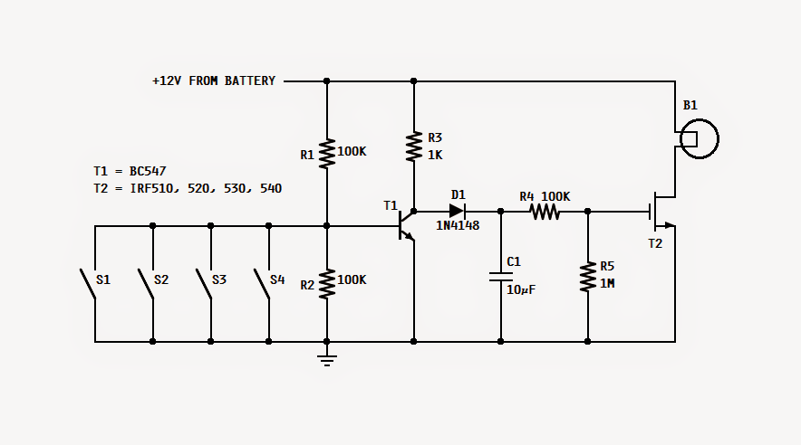
Making reference to the recommended car interior light fader circuit, when any of the door is opened, its switch is closed for this reason, the base of T1 gets linked with ground as well as stop executing. In this particular state, C1 gets charged swiftly with the aid of R3 and D1.

Immediately after C1 is charged, the mosfet is fed with the gate voltage thru R4 and thus it commences executing and consequently the lamp is activated.

Currently, when that door is closed, its switch gets open. The base of T1 gets turned off from the ground which is held at a voltage supplied by the R1/R2 voltage divider.

This action switches on T1, and the voltage that come from R3 confirms it way to ground thru emitter of T1.

The activating of T1 deprives C1 of its charging current and thus C1 starts off discharging steadily thru R4 and R5. The gate voltage of T2 lessens as C1 produces.

With this particular decline in the gate voltage the power of the lamp is also lowered. Lastly, when the gate voltage goes below the threshold voltage the lamp switches off.

The values of R5 and C1 should take care of the fading delay time of the lamp. Increasing the values increases the precious time and vice versa.

T2 should be any suited N-channel mosfet suitable for controlling no less than 50V and 10A. The complete circuit is generally constructed on compact sized general purpose board and enclosed in the room lamp cover.

You'll also like:

  • 1.  Garage Stop Light for Preventing Car Collision with Walls
  • 2.  Keep Car Battery Warm using this Circuit
  • 3.  Car Engine Overheating Alarm Circuit
  • 4.  Car Interior Lights Delay Off Circuit
  • 5.  How to Make a Solar E Rickshaw Circuit at Home
  • 6.  How to Make a Bicycle Horn Circuit with Ringtone

About Admin

Hey friends, Thanks a bunch for stopping by this site! I am an engineer with a Bachelor of Engineering in Electronics and Telecommunication. One of my passions is gathering information from all sorts of electronics books and tutorials. I then take that information and compile it into a language that is super easy to understand. My goal is to make those complex electronics circuit concepts and technical terms much more accessible for all the new and budding electronics engineers out there. I can also design customized circuit diagrams as required by the users.
If you have any questions related to this field, please do not hesitate to drop a comment! I am always here and ready to help you out with any queries you might have. I cannot wait to hear from you!

Reader Interactions

Leave a Reply Cancel reply

Your email address will not be published. Required fields are marked *

Primary Sidebar

Categories

  • 3 Phase (4)
  • 8051 Microcontroller (1)
  • Arduino (11)
  • Audio and Amplifier (102)
  • Automation (8)
  • Battery Chargers (64)
  • Bicycle Projects (4)
  • Car and Motorcycle Projects (39)
  • Datasheets (10)
  • DIY Projects (5)
  • Electrical (15)
  • Free Energy (6)
  • Games Projects (2)
  • High Voltage (14)
  • Hobby Projects (30)
  • Household Circuits (2)
  • IC 555 Circuits (5)
  • Ignition Circuits (2)
  • Indicators (50)
  • Infrared (6)
  • Inverter Circuits (29)
  • Lights and Lamps (97)
  • Medical (8)
  • Meter and Tester Circuits (38)
  • Motor Driver (17)
  • New Circuits (56)
  • Oscillators (30)
  • Pets and Pests (5)
  • Power supply (80)
  • Protection Circuits (25)
  • PWM (9)
  • Remote Control (20)
  • Security and Alarm Circuit (48)
  • Sensors and Detectors (66)
  • Signal Processor (23)
  • Solar Controller Circuits (62)
  • SSR (3)
  • Temperature Controller (20)
  • Timer (25)
  • Transformerless (7)
  • Transmitters (12)
  • Tutorials (45)
  • UPS (2)
  • Voltage Regulators (57)
  • Water Sensor and Controller (29)
  • Home
  • Privacy Policy
  • Contact
  • Disclaimer
  • Copyright

© 2025 · Making Easy Circuits