Here we are going to see one small but very useful car safety circuit which is actually made for warning the car driver much before the radiator gets overheated. That means that before the car engine temperature crosses the danger level, this circuit will already start ringing a buzzer and inform the driver. This can help to avoid engine damage or break down.
How This Circuit Actually Works
So the working of this idea is very easy to understand. It works directly using the 12V from the car battery. The main active part used here is our very familiar IC 555, which is acting like the brain of the circuit.
In this design we are using one thermistor as the sensor. That thermistor is connected in such a way that it controls the pin 2 of the IC555. Now what happens is when the thermistor senses that the temperature is going above one pre-fixed level, then it triggers the pin 2 of the IC. That makes the IC output go high. So immediately the output pin becomes high and it activates the buzzer and gives us a warning sound.
To decide at what temperature the buzzer should ring, we can adjust the variable resistors. That we can do using a 12V variable power supply during testing time.
How We Can Set This Circuit Properly
For setting or calibrating this circuit, we can use one small candle flame. But very important... YOU MUST NOT BRING THE THERMISTOR TOO CLOSE TO THE FLAME. If the thermistor touches too much heat or fire directly, it can get damaged permanently. So always keep the flame at a little distance.
Once the buzzer starts ringing during this test then we can assume that the circuit is working correctly. After the test, make sure to clean the thermistor surface properly, because some black soot may get deposited on it.
After Setup, How We Can Install Everything
Once the setting part is over, then we can keep the full circuit inside one small plastic box. Just make sure to give holes for wires – one for power input and one for the thermistor sensor wire.
Now put the thermistor near the car radiator pipe or close to any part which heats up fast. The main circuit board with buzzer can be fixed somewhere inside the car dashboard.
If you feel that using the car key switch is too complicated for powering this circuit then you can also use one small push switch or toggle switch. That switch can be connected directly to the car battery. But in that case, you will have to remember to manually switch on the circuit every time you start the car.
Circuit Diagram
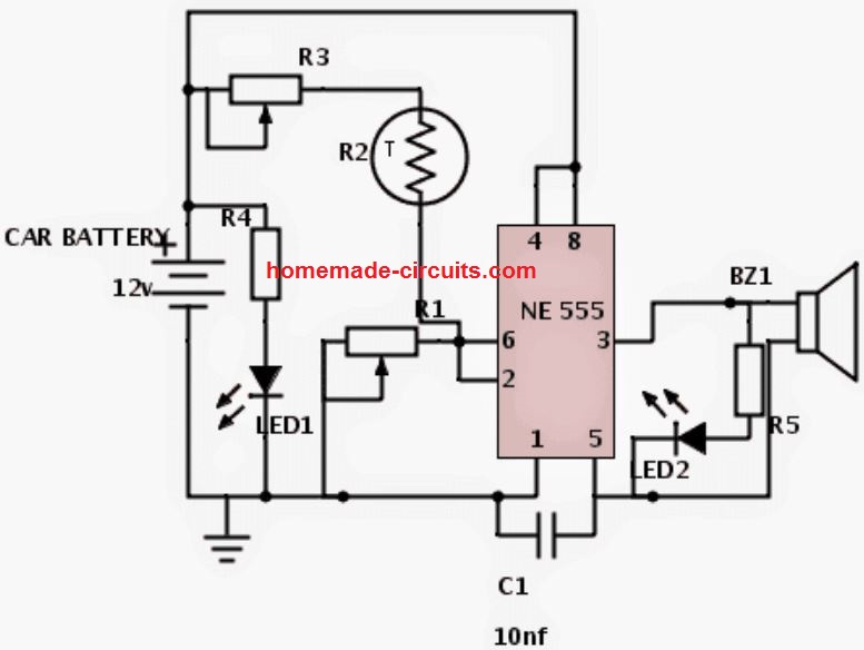
Parts List
- R1-5k variable resistor,
- R2-NTC thermistor, 50k,
- R3-5k variable resistor,
- R5-470ohms,
- LED1-green,
- LED2-red,
- C1-10nf.
How to Build
So now let us see how we can actually make this car radiator overheat alarm circuit in real using basic parts and small tools.
First Step – Get All Parts Ready
So before we start building, we must collect all the required parts like IC 555, thermistor, resistors, variable resistors (preset), small buzzer, and a few wires. Also we need one small piece of general purpose PCB (zero board) to fix everything properly. Keep one 8-pin IC socket also if you want to protect the IC.
Second Step – Solder the IC and Surrounding Parts
Now take the PCB and place the IC socket in the center. Solder it first. Then slowly start adding the resistors, variable resistor and capacitors as per the circuit diagram around the IC. Use proper jumpers or small wire links wherever needed. Make sure pin numbers are correct. Use one buzzer on output pin 3.
Third Step – Thermistor and Power Connections
Take the thermistor and connect it with long flexible wires so that we can keep it away from the main circuit later. Solder it nicely at the correct point where the diagram shows. After that connect the power supply wires, positive and ground wires which will go to car battery or switch.
Fourth Step – Testing Time
Before fixing permanently, we must test. Power the circuit using one 12V DC adapter. Bring one small candle near the thermistor and check if buzzer rings when heat comes close. If not, then adjust the variable resistor slowly until the buzzer rings at proper temperature.
Fifth Step – Final Fixing and Casing
After testing is successful, put the full board inside one small plastic box. Make two small holes – one for power wire and one for sensor wire. Use glue or hot glue to fix the thermistor wire strongly so that it does not break later.
Last Step – Install Inside Car
Fix the thermistor near radiator using tape or zip tie. Keep the plastic box with buzzer inside dashboard or under the steering safely. If needed add a small manual switch to control power.
Leave a Reply