Imagine a motor boat running all around in your room. For this you neither need water nor a big bulky wooden frame with a heavy engine fixed to it, but just this electronic pocket sized gadget.
It produces notes resembling that of a running motor boat. These notes can be adjusted by a knob to get proper effects of starting of engine, throttling of engine etc.
The whole assembly can be assembled in a small cabinet with the controls at the top for easy operations.
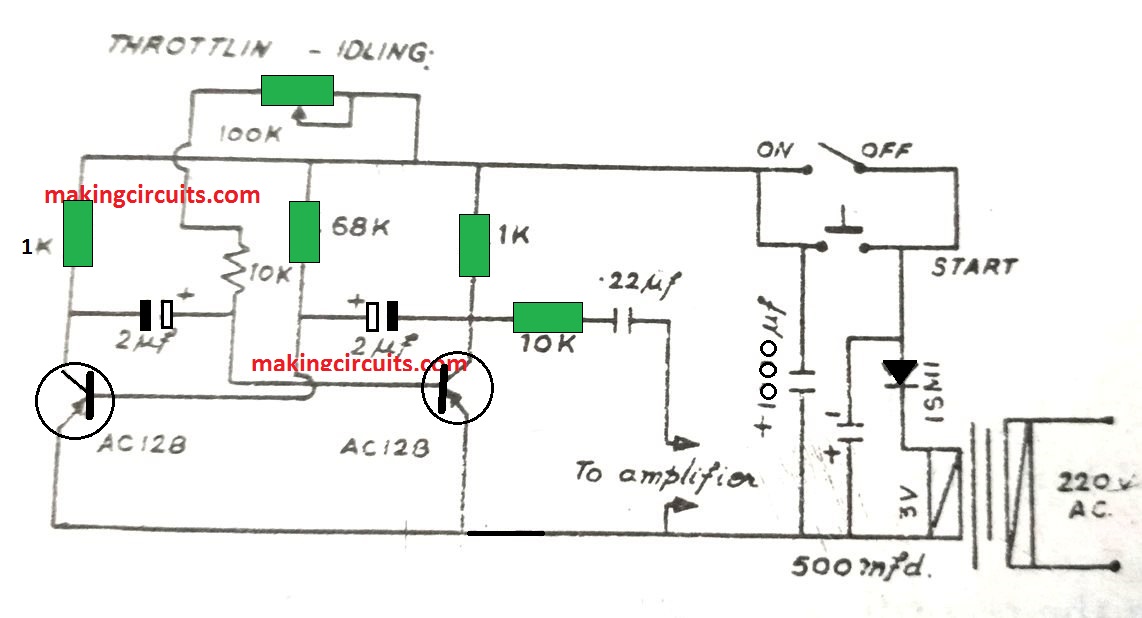
The control can be marked as ON/OFF, Start, Idling, Throttling.
The output from the unit is connected to the input of any power amplifier or radio pick up.
The volume of the amplifier is adjusted to the desired value.
To start off the motor boat press the start button momentarily, this will result in a few "phut" phut" notes.
Do it once or twice so as to get the effect of that warming up of the engine.
To start, switch ON the ON/OFF switch and a continuous slow "phut phut" will occur.
This sound sounds like that of an idling engine.
Now, for throttling, turn the potentiometer gradually so that an increase in the rate of phut phut is obtained.
The heart of the unit is a free running multivibator. The frequency of the multivibrator is adjusted by the potentiometer, whih in turn produces the throttling effect.
The start push button connects the supply across the condenser and when pressed, charges the capacitor to the supply voltage.
The charge stored in the capacitor is sufficient to operate the unit for s few seconds after whch it discharges.
This results in s few "phut phuts" which gradually die off giving an effect of that of a starting engine.
On switching the ON/OFF switch to ON position, the power supply gets connected to the unit; continuous low frequency phut-phut notes are produced which indicate that the engine has started and is now idling.
In order to accelerate the engine, rotate the potentiometer knob.
With an decrease in resistance the phut-phut rate increase.
For stopping the motor boat engine, switch OFF the power supply (ON/OFF switch).
The phut-phut sound then gradually dies off.
The coupling capacitor connected in series with the output prevents the DC from flowing through it buts allows the pulses to pass through it. he connections of the switches are also shown in the circuit diagram below:
Parts List
Transistors:
2N2222 - 2nos
Capacitors:
470uF/16V - 1no
1000uF/16V - 1no
2.2uF/16V - 2nos
0.22uF/50V - 1no
Resistors (1/4 watt 5%):
1K - 2nos
10K- 2nos
68K - 1no
Potentiometer - 100K Linear - 1no
Diode: 1N4007
Step down transformer = 3V / 100mA
Push-On Switch - ON/OFF switch
Jonathan says
Exactly what I needed! Were suprised that someone already had done it:) I Removed the diode and the 470uF capacitor to run it strait on 3vdc and also lowered the 64k resistor to rew it a bit higher:) Thanks for the simple circuit that will make the kids happy 🙂
admin says
Thanks for your feedback, I am Glad it helped you, wish you all the best!