In this article we will build an easy 12V 100Ah lead acid battery charger circuit which will give you 10A of current. The article discusses 3 unique charger circuits; you might develop the one that fits your condition.
How to Charge High Current Lead Acid Batteries
It is crucial to understand exactly how charging of high Ampere-Hour lead-acid batteries are accomplished, before you decide to jump into the design information on chargers. Correct knowledge will assist you to figure out at precisely what voltage, at what current the battery must be charged and the time it will need to cut-off from the charger. This will ensure that your battery will likely be recharged optimally and also have significantly less possibility of untimely degradation.
Lead-acid batteries are charged in three stages:
- Constant current.
- Constant voltage.
- Trickle charging.
We need to go through the charging characteristics graph of a lead acid battery:
- Lead Acid battery charging characteristics
- Lead Acid battery charging characteristics
- Constant current charging:
A 12V battery is normally recharged at 14.2 V or 2.40V per cell. Once we attach the charger with the battery, voltage drops from the actual supply 14.2 V level to the discharged level of the battery. As the battery gets charged the terminal voltage begins increasing gradually, until it reaches the set 14.2 V. However, current drawn from the charger will be at the specified rate (For example if the input 10 amp, the consumption will initiate with 10 amp rate.)
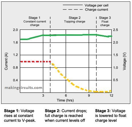
In the graph as given in battery university you observe a straight portion of the red line signifies the current this also constant as time passes. This portion of charging procedure is referred to as constant current charging. 70 PERCENT of the battery will be charged in the course of CC period.
Constant voltage charging:
The green-colored line in the graph signifies the voltage of the battery that increases in the course of charging. In the position (14.4V) when the voltage will be constant. Subsequently the current will begin to decrease speedily, this is represented by the orange dotted line. This period is known as constant voltage charging. The rest 30% of the battery will be charged during this phase.
Note: Changeover from constant current to constant voltage phase happens the natural way.
Trickle charging:
Trickle charging is performed by making use of current equal to self-discharge rate of battery. It is accomplished with no load connected.
When should you disconnect the battery from the battery charger?
The battery must be totally cut-off from charger or it must be trickle charged at reduced current once the charging current extends to 3% of the battery capacity (Ah).
As an example, a 100Ah battery must be cut-off any time charging current minimized to 3A. A 200Ah battery must be cut-off when charging current gets to 6A. Charging over and above this may harm the battery.
NOTE: By measuring just the voltage is not going to inform us if the battery is completely charged or not. It's the current which reveals the actual condition of charge.
How to Calculate Charging Current for Lead-Acid battery?
Charging current for just about any lead acid battery has to be according to manufacturer’s proposition. On the other hand charging the battery lower than particular current is not going to hurt the battery but it is going to take more time to achieve full charge.
Charging current for lead acid batteries is usually from 10% to 25% of the volume.
For instance: When you have 100Ah battery it is possible to charge it at 10A. For those who have 200Ah battery it is possible to charge at 20A, and so on.
You can take advantage of this formula: Charging current = 1/10 x Ah.
How long it will take to charge a battery?
Let's suppose, the battery is discharged (not over discharged) you can apply this formula:
Hours = Ah / Charging Rate
For example:
Hours = 100A / 10Ah = 10 hour.
It is best to measure the current to ascertain if the battery is completely charged or not.
Congratulations, now you fully understand, at what current and voltage the battery should be charged for an available capacity of lead-acid battery. You understand when should you cut-off the battery from the source voltage and you likewise have obtained a rough idea regarding how much time it requires to charge a battery fully.
3 Ways to Charge a 12V 100 Ah Battery
The following 3 simple circuit diagrams will explain how to charge a 12V 100 Ah lead acid battery safely and cheaply without causing any harm to the battery. These circuits will also ensure a long life for your battery
Using LM317 and Outboard Current Boost Transistor
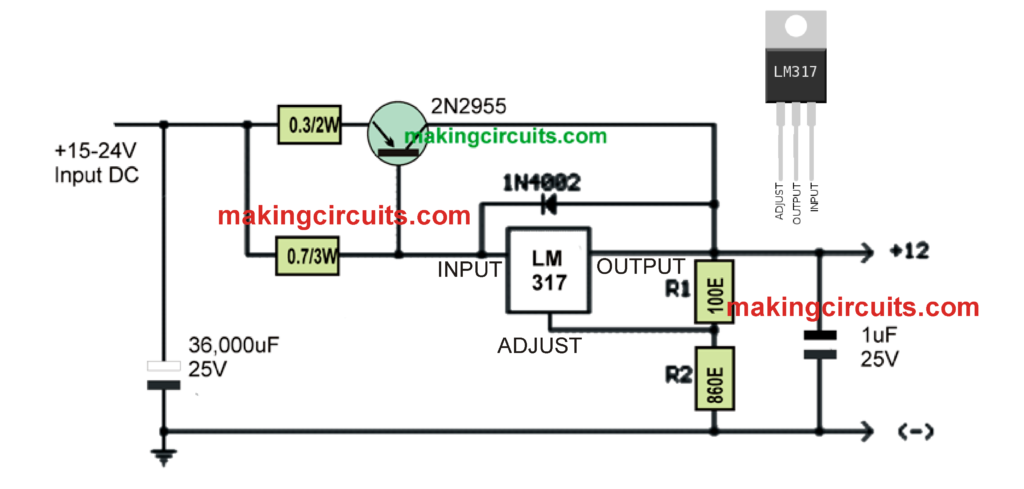
The above circuit looks pretty simple, yet has the ability to charge a 12 V 100 Ah battery with utmost efficiency.
We all know how efficient the IC LM317 is, and moreover this IC is easily available and cheap.
Although LM317 alone will be unable to provide the required 10 amp current, the inclusion of the PNP power transistor enhances the capacity of the circuit 10 times more and allows it to handle current as high as 10 amps and above.
Please make sure to tweak the R2 value so that the output is adjusted to 14.2 V.
The output current can be adjusted by adjusting the value of the 0.3 ohm resistor. This will need to be done with some trial and error.
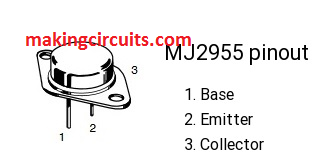
The pinout details of the 2955 transistor can be learned below:
Using 2N3055 Transistor
The next 12V 100 Ah lead acid battery charger shown below is probably simpler than the above.
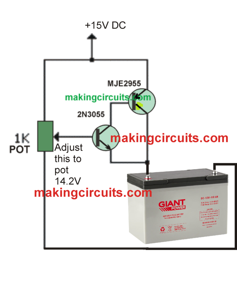
In this schematic we can see a couple of complementary power transistors are used in a high current gain mode. Here we have employed the popular 2N3055 and its complementary 2N2955 together to create a high gain pair for delivering the required 10 amps to the battery for an efficient charging.
However, make sure that the input supply current is constant at 10 amps.
Using an 7815 Voltage Regulator
OK, do you have a 7815 voltage regulator IC in your junk box. If you do, you can quickly design a high current 100 Ah charger by simply combining it with any 15 amp PNP transistor such as the above discussed 2N2955.
You can find the circuit diagram below:
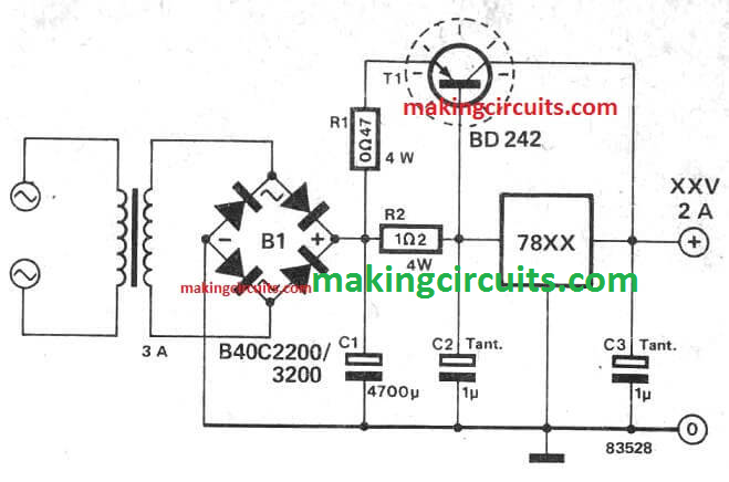
The above circuit is calculated for a 2 amp outpur, but you can easily upgrade it for delivering upto 10 amps easily so that it becomes suitable for charging our 12V 100 Ah battery.
To get all the details of the calculations you can refer to the table provided in this article
Tim says
I would like to make your circuit: “Using LM317 and Outboard Current Boost Transistor” but I don’t understand your use of some technical terms on your circuit diagram (please understand I’m barely more than a novice when it comes to electronics!).
Please explain the meaning of the label that says: 0.3/2W
Please explain the meaning of the label that says: 0.7/3W
Please explain the meaning of the label that says: 100E
Please explain the meaning of the label that says: 860E
Would a power transistor of similar spec to the 2n2955 be acceptable in this circuit?
Finally, the capacitor on the input seems to be an extremely high value of 36,000uF, is this correct?
Many Thanks for your help.
admin says
1) that is a resistor
2) that is a resistor
3) 100E = 100 ohms
4) 860 E = 860 ohms
5) yes acceptable
6) you can simply replace it with a 1000uF/25V capacitor
joseph h dietz says
can i charge the 12v 100ah solar lead battery with a battery charger or should i trickle charge it? ty
admin says
You should charge it with a battery charger, as explained in the above article
SAJI TR says
I think this is not a solar controller charger circuit diagram
admin says
It can be used as a solar controller by adding a solar panel to the input side of the circuits