This blog article describes a circuit that Mr. Raj constructed for a 12V, 100Ah battery charger. The article looks into the operation of the circuit and considers its possible use as a trickle charger circuit.
Technical Specifications as Explained by Mr. Raj
I just came onto your blog and I'm writing from Mumbai. I've been reading it frequently and have found your postings to be quite educational.
For my own usage, I want to create a battery charger. I have a 10 amp transformer with two 9 volt outputs (18 volts total) and an 80Ah deep cycle battery that I rescued from an old UPS.
I designed a circuit based on the information in your blog (attached). I would appreciate it if you could examine it and provide some guidance.
Here are some more information to think about:
Power Variations: The power variations in the rural area where I reside are substantial, varying between 50V and 250V.
Low Current Draw: I only want to utilize the battery (around 15-20 watts) for low-power devices like LED lights during blackouts.
Transformer Capacity: I think my 80Ah battery can be securely charged using a 10-amp transformer.
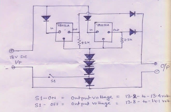
Rectifier Diodes: The circuit's diodes are all 6A4 diodes.
Utilizing two 78H12A voltage regulators in parallel, I was able to obtain a total output of 10 amps (5 amps each regulator).
I am aware, though, that the batteries probably won't need all 10 amps when charging.
Trickle Charge Switch: After the battery has reached full charge, the switch (S1) is designed to be used for both regular charging (off) and trickle charging (on).
I wonder if the battery will be okay if the charger is left in trickle mode for a long time.
Regarding my circuit design, I would much appreciate your opinions and any recommendations you may have.
Regards, Raj.
Simple 100 Ah battery charger circuit designed by Mr. Raj
Addressing the Issue
Hello Raj
On paper, the VRLA battery charger circuit you created using the 78H12A ICs appears to be a nice one! Before attaching it to your batteries, it's a good idea to use a meter to check the output voltage and current just to be sure.
The following are some ideas for enhancements:
Trickle Charging: Trickle charging is possible with this switch. You can leave the charger in this mode for extended periods of time (but only until the battery reaches 14.3 volts, which is full charge).
Diodes: You may use standard 1N4007 diodes for the four diodes that are attached to the ICs' ground (GND) pins.
The other diodes, however, require a current rating greater than 10 amps. For each of those spots, you may do this by connecting two of your 6A4 diodes in parallel.
Heatsink: Mounting both integrated circuits on one sizable heatsink is strongly advised. They will be able to share the heat burden and disperse it more efficiently as a result.
Important Safety Notice: There is no automatic shut-off mechanism for this circuit when the battery runs out of power. It's critical to keep the maximum charging voltage between 13.8 and 14 volts to avoid overcharging.
In addition to ensuring the battery's safety, this will prevent it from reaching its maximum capacity.
Trade-off: The battery will only fully charge to around 75% if the charging voltage is limited. Nonetheless, the battery will last longer and be able to withstand more charge/discharge cycles overall because to this undercharging.
How to Charge a 100 Ah Battery with a 2N3055
A simple and dependable way to charge a 100Ah battery is provided by this circuit. It makes use of a 2N3055 transistor to provide a constant current, making sure the battery gets the right amount of charge.
The circuit design makes use of the emitter follower arrangement of the 2N3055. Effectively preventing overcharging, the transistor automatically decreases its functioning to near-off state when the battery achieves its maximum charge level.
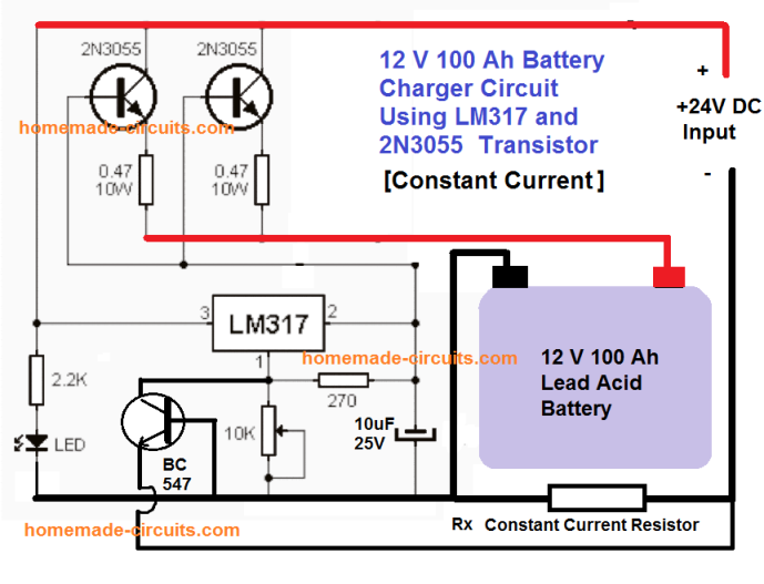
The following formula can be used to determine the current limit:
R(x) = 0.7 / 10 = 0.07 Ohms
Wattage will be = 10 watts
Easy Ways to Include a Float Charge
Other websites that overcomplicate the idea of float pricing may be encountered. For a clearer explanation, see this:
What is essentially a low-level current that maintains a fully charged battery topped off and inhibits self-discharge is called "float charging."
Self-Discharge: What Is It? Consider it as the battery's inherent propensity to gradually discharge even when not in use.
The Solution: Place a high-value resistor (such as 1 kΩ or 1 watt) between the battery's positive terminal and the 15V power supply to stop this from happening. As long as the resistor is connected, it permits a very little amount of trickle current to pass, keeping the battery's voltage at around 14V.
Leave a Reply