This post explains exactly how to construct a basic railway signal light that guards may use to provide handheld signals to different trains using a variety of signaling types. Mr. Danny asked for the concept.
Electrical Details
I require a railway led signaling light project layout. There must be four modes on the light. 1) Red stable 2) Steady green 3) bursts of red 4) Green blinks likewise indicate that the circuit is charged appropriately.
The setup
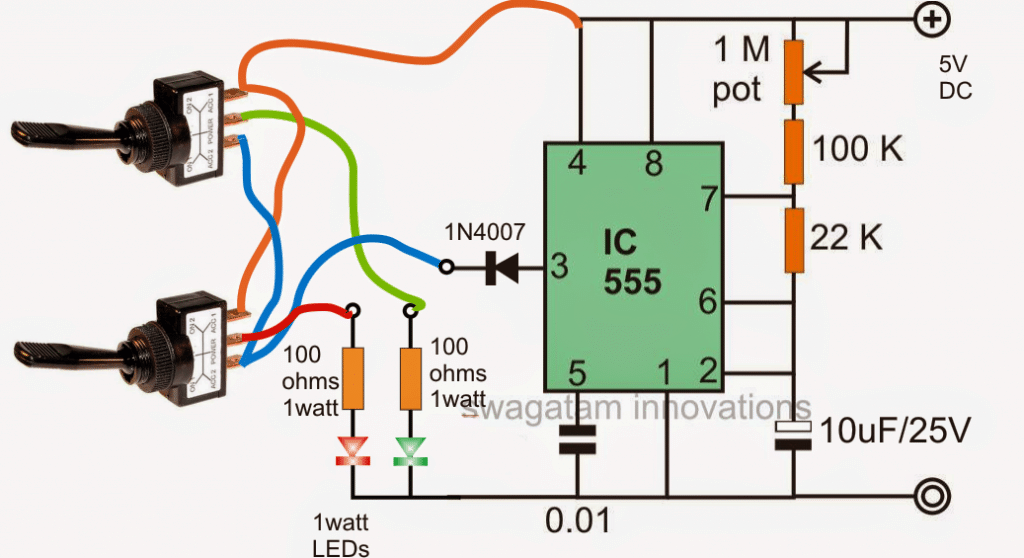
A straightforward IC 555 astable circuit may be used to build the suggested railway signal lamp circuit with blinking LEDs, as seen below:
Circuit Diagram

If we take a look at the diagram that is provided above we can start to understand how the circuit operates as I will explain in detail below.
Circuit Operation
The integrated circuit known as the IC 555 is set up in what is commonly referred to as its standard astable mode.
This configuration is designed specifically to generate an alternating ON and OFF potential at pin number three of the IC.
This particular IC has impressive capabilities and is rated to deliver a current of up to approximately two hundred milliamperes.
Because of this rating one watt LEDs are perfectly suitable for being connected directly to this specific pinout of the IC.
Now since these one watt LEDs are rated to handle a current of three hundred fifty milliamperes the lower amount of current that is available allows these LEDs to operate without the need for heatsinks.
However even with a current of one hundred milliamperes it can be expected that the light emitted from these LEDs will be significantly bright making them quite appropriate for the railway safety signal lamp application that has been requested.
In this setup there is a one megohm potentiometer which is utilized to adjust the flashing rate of the LEDs.
Additionally there are switches that determine the operational modes of the LEDs according to the specifications that have been requested.
It is important to note that the switches should be of the single pole double throw type and must include a center off feature.
When you toggle the relevant switches downwards it results in a constant switched ON response from the LEDs.
On the other hand if you toggle them to the lower side it allows the LEDs to flash.
The center off feature of these switches can be conveniently used for keeping the LEDs turned off when they are not needed.
To further enhance performance it is essential that the LEDs are housed inside high gloss reflector cones.
This design choice will help achieve an improved light output and will also increase the visibility range significantly.
Leave a Reply