A simple short wave radio with high sensitivity is narrated in this post and be built by any radio enthusiast.
The consequences of regeneration of the regenerative TRF receivers are the radiation and unwanted coupling of the antenna and the L-C circuit. During tuning of the antenna input, miller-effect of the RF stage adds more to the effect of unwanted coupling. Those having a degree in gymnastics this TRF regenerative design suits them, in shortwave especially.
Circuit Working
The short wave radio receiver could also be used in oscillating mode by reducing the effect of oscillations caused by unwanted coupling to about 100 Hz.
The oscillating mode may provide the owner various product-detector reception modes, namely CW, RTTY and SSB. If a frequency counter is added, this feature can be more pronounced.
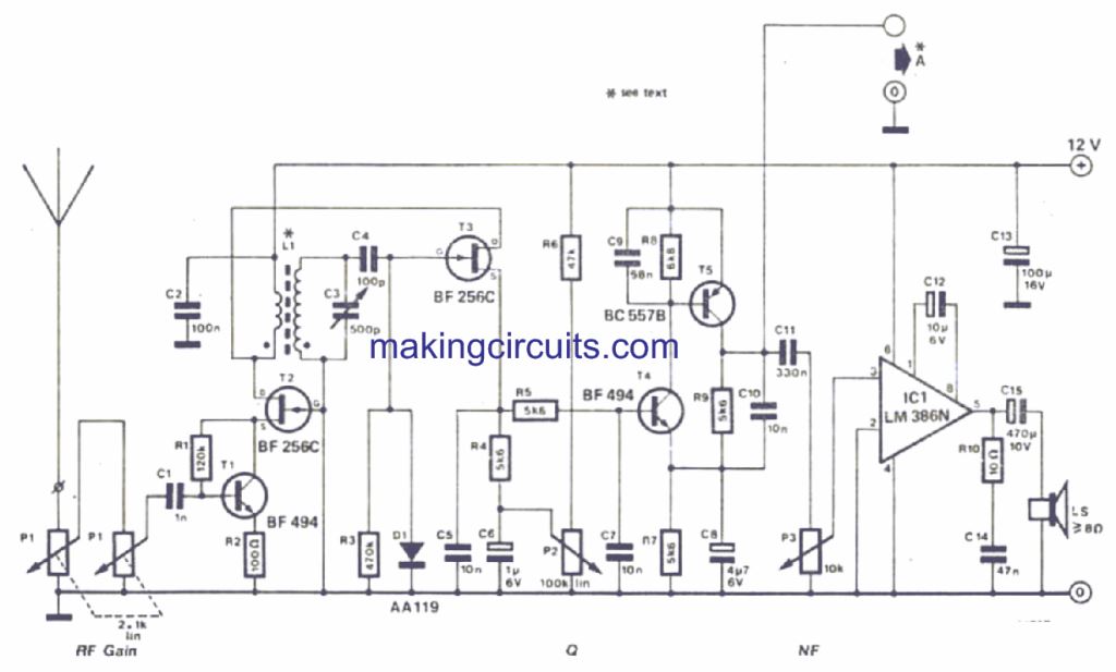
To minimize the pulling, a bipolar transistor and a FET connected in series are added to the RF stage of the circuit as shown in figure. It can be observed that the input is aperiodic.
The disadvantage of input overload is more than compensated for by the high sensitivity ( a tiny whip antenna can be enough). Regeneration is counter-acted by lowering its transconductance.
The counter-acting process starts with D1 helping in smooth control over regeneration and on reaching the threshold voltage a negative bias is supplied for T3, thereby lowering its transconductance.
As the detector used is an infinite impedance detector it can cope up with relatively strong input signals. Therefore, for a heavily modulated(AM) carrier, distortion will be low.
Specifications for the prototype :-
- Single sensitivity (AM mod. 30%, S/N = 10dB): 1mu(= 10^-6) V
- Single signal sensitivity (SSB, S/N = 10dB): 0.3muV
- frequency range with a 500p
- Tuning capacitor: 4.4 to 17 Mhz
Sensitivity Range
Single signal sensitivity is the value obtained by measurement of sensitivity with the help of a signal generator when all other signals are absent. In countries like Australia, spectrum is not polluted by OTHR' S and BC jammers. But in other countries except Australia, full benefit of this sensitivity can never be obtained because on strong adjacent channel signals envelope detection takes place and also input overloading of wideband RF stage.
Depending on tuning, the suppression can be of the order between 40 to 60 dB in the product detector mode. Lower value indicates the highest tuning frequency. By reducing the L/C ratio, it can be more improvised.
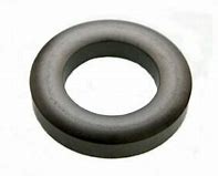
An amidon ring core type T94-6 is used which has 6 turns of an enameled copper wire 0.25mm in size that forms primary winding of L1. Over the length of the core 25 turns of 0.68-0.8mm enameled copper wire is winded that forms the secondary winding. Primary winding should be layered between turns of the secondary and should be at the 'cold' end.
Leave a Reply