• Skip to main content
  • Skip to primary sidebar

Making Easy Circuits

Learn and build electronic circuits

You are here: Home / New Circuits / 0 – 30 V Regulated Power Supply Circuit

0 – 30 V Regulated Power Supply Circuit

Last Updated on April 15, 2020 by Admin 3 Comments

This 0 - 30 V regulated work bench power supply provides outstanding line and load regulation and a continuously variable output from 0 to 30 V with output currents as much as one amp. The output features current limiting and is also protection against reverse voltage or over-voltage placed on the output terminals.

Circuit Description

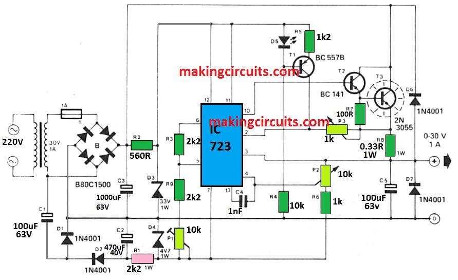
The circuit is centered around the popular 723 IC regulator. As visitors who may have implemented this IC will be aware, the lowest output voltage typically accessible from this chip is + 2 V in accordance with the V - terminal of the IC (that is generally attached to 0 V).

0 to 30 V 723 power supply circuit

The issue could be corrected by joining the V - pin with a minimum negative potential of around - 2 V, in order that the output voltage may drop down to +2 V in accordance with this, i.e. to zero volts.

To refrain from using a transformer having many secondary windings, the additional negative supply is acquired through a voltage doubler set up containing C1, C2, D1 and D2 and is regulated at -4.7 V through R1 and D4.

The utilization of - 4.7 V instead of -2 V signifies that the differential amplifier inside the IC 723 continues to work nicely using its common-mode range regardless if the output voltage is zero.

The primary positive supply voltage is extracted from the transformer by means of bridge rectifier B1 and reservoir capacitor C3. The source to the IC 723 is stabilized at 33 V by means of D3 in order to avoid its highest supply spec becoming maxed and a Darlington pair T2/T3 enhances the output current functionality to 1 A.

The current limit is consistently adjustable through P3. The output voltage could be tweaked through P2, although preset P1 can be used to get zero output voltage. The input supply is guarded against reverse polarity being utilized to the output wires by means of D7, and to resist over voltages as much as 63 V by D6.

To pre adjust the output voltage to zero, P2 is initially flipped anticlockwise (wiper rotated in the direction of R8) and P1 is after that tweaked until the output voltage becomes zero.

Having P2 moved totally clockwise the output voltage must subsequently be around 30 V. In case, on account of component limitations, the optimum output is seen lower than 30 V the R6 value might need minor lowering.

While building the 0 - 30V regulated power supply circuit, specific attention must be implemented to guarantee that the 0 V line is of minimal resistance (large SWG cord or broad PCB track) as voltage falls alongside this power rail could potentially cause bad regulation and ripple on the output.

You'll also like:

  • 1.  Automatic Central Heating Controller Circuit
  • 2.  How to Make a Cellphone Jammer Circuit Explored
  • 3.  How to make a Temperature Triggered DC Fan Speed Controller Circuit
  • 4.  How to Modify a Bluetooth Headset Device for Personalized Applications
  • 5.  Build this Hartley Oscillator Circuit
  • 6.  How to Change Fluorescent Tubes to LEDs

About Admin

Hey friends, Thanks a bunch for stopping by this site! I am an engineer with a Bachelor of Engineering in Electronics and Telecommunication. One of my passions is gathering information from all sorts of electronics books and tutorials. I then take that information and compile it into a language that is super easy to understand. My goal is to make those complex electronics circuit concepts and technical terms much more accessible for all the new and budding electronics engineers out there. I can also design customized circuit diagrams as required by the users.
If you have any questions related to this field, please do not hesitate to drop a comment! I am always here and ready to help you out with any queries you might have. I cannot wait to hear from you!

Reader Interactions

Comments

  1. johnny says

    March 17, 2025 at 10:42 pm

    it works pretty good
    thank you

    Reply
  2. Jan says

    February 26, 2025 at 3:59 pm

    Hello.Is the current setting so? Short circuit on the output and then I adjust the current.The LED D5 will turn on when I will reach the adjusted current.
    Thank you for the answear.

    Reply
    • Admin says

      February 28, 2025 at 8:33 am

      Hey Jan, I don’t think the LED indicates the current limiting status. I guess the D5 with T1 is used to supply a constant current reference to the IC.

      Reply

Leave a Reply Cancel reply

Your email address will not be published. Required fields are marked *

Primary Sidebar

Categories

  • 3 Phase (4)
  • 8051 Microcontroller (1)
  • Arduino (11)
  • Audio and Amplifier (102)
  • Automation (8)
  • Battery Chargers (64)
  • Bicycle Projects (4)
  • Car and Motorcycle Projects (39)
  • Datasheets (10)
  • DIY Projects (5)
  • Electrical (15)
  • Free Energy (6)
  • Games Projects (2)
  • High Voltage (14)
  • Hobby Projects (30)
  • Household Circuits (2)
  • IC 555 Circuits (4)
  • Ignition Circuits (2)
  • Indicators (50)
  • Infrared (6)
  • Inverter Circuits (29)
  • Lights and Lamps (97)
  • Medical (8)
  • Meter and Tester Circuits (38)
  • Motor Driver (17)
  • New Circuits (56)
  • Oscillators (30)
  • Pets and Pests (5)
  • Power supply (81)
  • Protection Circuits (25)
  • PWM (8)
  • Remote Control (20)
  • Security and Alarm Circuit (48)
  • Sensors and Detectors (66)
  • Signal Processor (23)
  • Solar Controller Circuits (61)
  • SSR (3)
  • Temperature Controller (20)
  • Timer (25)
  • Transformerless (7)
  • Transmitters (12)
  • Tutorials (45)
  • UPS (2)
  • Voltage Regulators (57)
  • Water Sensor and Controller (29)
  • Home
  • Privacy Policy
  • Contact
  • Disclaimer
  • Copyright

© 2025 · Making Easy Circuits