• Skip to main content
  • Skip to primary sidebar

Making Easy Circuits

Learn and build electronic circuits

You are here: Home / Lights and Lamps / 1.5V LED Flasher Circuit

1.5V LED Flasher Circuit

Last Updated on September 22, 2021 by Admin 3 Comments

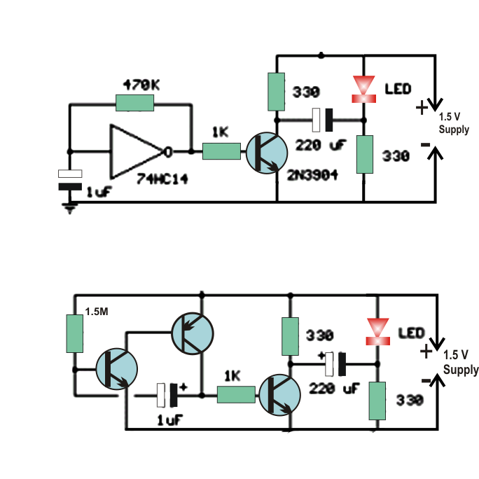
This LED flasher circuit requires only 1.5V to flash an LED lamp and therefore can be operated using a single 1.5V AAA cell.

The upper circuit, shows utilizing a 100uF capacitor to twofold the battery voltage to get 3 volts for the LED.

How the Circuit Works

Two segments of a 74HC04 hex inverter are utilized as a squarewave oscillator that determines the flashing rate while a third stage is utilized as a soft start that charges the capacitor in arrangement with a 470 ohm resistor, while the support yield is at +1.5 volts.

At the point when the slow start yield changes to ground (zero volts) the charged capacitor is put in arrangement with the LED and the battery which supplies enough voltage to light up the LED.

The LED current is more or less 3 uF, so a high watt LED is suggested.

In the other circuit, the same voltage multiplying standard is utilized with the upgrading the transistor to permit the capacitor to provide speedier supply higher current (around 40mA crest).

A bigger capacitor (1000uF) in arrangement with a 33 ohm resistor would expand the glimmer length of time to around 50mS.

The discrete 3 transistor circuit at the lower right would require a resistor (around 5K) in arrangement with the 1uF capacitor to increase the flashing pulse width.

1.5 V LED flasher

You'll also like:

  • 1.  Decorative Flashing LED Circuit
  • 2.  How to Build a Automatic Fish Aquarium Light Optimizer Circuit
  • 3.  6v DC 20 watt Florescent Lamp Driver Circuit
  • 4.  220V Transformerless LED Driver Circuit
  • 5.  Making a 10w, 12w LED Lamp with Fixture
  • 6.  9V Tubelight Inverter Circuit

About Admin

Hey friends, Thanks a bunch for stopping by this site! I am an engineer with a Bachelor of Engineering in Electronics and Telecommunication. One of my passions is gathering information from all sorts of electronics books and tutorials. I then take that information and compile it into a language that is super easy to understand. My goal is to make those complex electronics circuit concepts and technical terms much more accessible for all the new and budding electronics engineers out there. I can also design customized circuit diagrams as required by the users.
If you have any questions related to this field, please do not hesitate to drop a comment! I am always here and ready to help you out with any queries you might have. I cannot wait to hear from you!

Reader Interactions

Comments

  1. Rich. says

    January 2, 2022 at 10:03 pm

    where can I buy all these things ?

    Reply
  2. Curious Someone says

    October 20, 2020 at 2:59 am

    The description does not match the actual circuit diagrams. For the 1st circuit you talk about THREE hex inverters but only one is drawn. You mention a 470 Ohm resistor but the diagram shows 470 KOhm. What is “the drove” ? What about a “Mama” never heard of that?

    In the 2nd circuit (three discrete transistors) you mention a 5KOhm resistor in series with a 1uF capacitor but the diagram shows a 1K resistor. You also mention about a bigger capacitor of 1000uF with a 33 Ohm resistor but the diagram shows 330 Ohm resistors and a 220uF capacitor.

    Reply
    • admin says

      October 26, 2020 at 1:00 pm

      thanks for the pointer, I did the corrections as much as possible,

      Reply

Leave a Reply Cancel reply

Your email address will not be published. Required fields are marked *

Primary Sidebar

Categories

  • 3 Phase (4)
  • 8051 Microcontroller (1)
  • Arduino (11)
  • Audio and Amplifier (102)
  • Automation (8)
  • Battery Chargers (64)
  • Bicycle Projects (4)
  • Car and Motorcycle Projects (39)
  • Datasheets (10)
  • DIY Projects (5)
  • Electrical (15)
  • Free Energy (6)
  • Games Projects (2)
  • High Voltage (14)
  • Hobby Projects (30)
  • Household Circuits (2)
  • IC 555 Circuits (5)
  • Ignition Circuits (2)
  • Indicators (50)
  • Infrared (6)
  • Inverter Circuits (29)
  • Lights and Lamps (97)
  • Medical (8)
  • Meter and Tester Circuits (38)
  • Motor Driver (17)
  • New Circuits (56)
  • Oscillators (30)
  • Pets and Pests (5)
  • Power supply (80)
  • Protection Circuits (25)
  • PWM (9)
  • Remote Control (20)
  • Security and Alarm Circuit (48)
  • Sensors and Detectors (66)
  • Signal Processor (23)
  • Solar Controller Circuits (62)
  • SSR (3)
  • Temperature Controller (20)
  • Timer (25)
  • Transformerless (7)
  • Transmitters (12)
  • Tutorials (45)
  • UPS (2)
  • Voltage Regulators (57)
  • Water Sensor and Controller (29)
  • Home
  • Privacy Policy
  • Contact
  • Disclaimer
  • Copyright

© 2025 · Making Easy Circuits