• Skip to main content
  • Skip to primary sidebar

Making Easy Circuits

Learn and build electronic circuits

You are here: Home / Power supply / +/- 15V Dual Regulated Power Supply Circuit

+/- 15V Dual Regulated Power Supply Circuit

Last Updated on April 14, 2020 by Admin 2 Comments

In this post we discuss how to build a simple, regulated fixed +/- 15 V symmetrical dual power supply circuit using standard components and very cheaply.

Despite the fact that IC voltage regulators have currently mostly replaced discrete part models, this circuit comes with a significant Cost benefit more than an IC regulator.

Circuit Description

Working of the circuit is incredibly straightforward. The centre-tapped transformer, bridge rectifier and smoothing capacitors C1 and C2 deliver an unregulated supply of around 20 V. The positive and negative regulators work in a similar fashion excluding polarity, therefore just the positive regulator is going to be explained in depth.

15 V dual power supply circuit

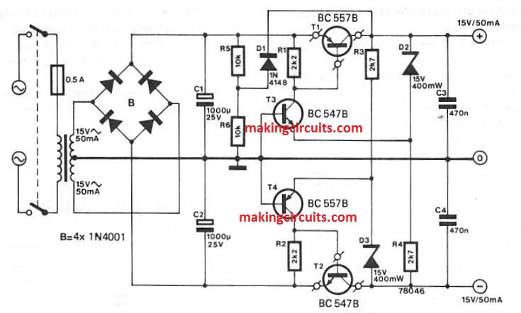
The positive supply current moves via a series regulator transistor T1. 15 V is lowered across zener diode D5, the top section being at around +15 V and the bottom end at 0 V. If the output voltage of the regulator happens to drop then the lower terminal of D5 may drop below 0 V and transistor T3 could pull higher current.

This can provide T1 with increased base current, switching it ON excessively in order that the output voltage of the regulator boosts up. When the regulator output voltage gets way too high then the opposite begins happening.

The potential at the D5 bottom terminal rises and T3 pulls lower current. T1 consequently begins deactivating and the source voltage drops.

The negative supply works in the same way. Considering that D5 and D6 obtain their bias through the supply output, R5 , R6 and D7 should be incorporated to enable the circuit to be self-starting.

A preliminary bias of about 10 V through the unregulated supply is supplied by all these parts. As soon as the supply output voltage rises to its typical value D7 gets reverse-biased, which inhibits ripple from the unregulated supply showing up around the output.

The indicated transistors for the +/- 15 V dual power supply circuit will allow only up to 100 mA current. For getting higher current you can simply change the upper and lower series pass transistor with TIP127 and TIP122 respectively or other similar variant, which will provide as high as 3 amp current output

You'll also like:

  • 1.  High Voltage Regulated Power Supply Circuit with Over Current Protection
  • 2.  Simplest Variable 0-100V Power Supply Circuit
  • 3.  Simple Crowbar Circuits for Over-voltage Protection
  • 4.  Surge free Transformerless Power Supply Circuit using zero Crossing Detection
  • 5.  Simple 0-24V/5Amp Variable Power Supply Circuit with Transistors
  • 6.  Constant Current Circuit for High Watt LEDs

About Admin

Hey friends, Thanks a bunch for stopping by this site! I am an engineer with a Bachelor of Engineering in Electronics and Telecommunication. One of my passions is gathering information from all sorts of electronics books and tutorials. I then take that information and compile it into a language that is super easy to understand. My goal is to make those complex electronics circuit concepts and technical terms much more accessible for all the new and budding electronics engineers out there. I can also design customized circuit diagrams as required by the users.
If you have any questions related to this field, please do not hesitate to drop a comment! I am always here and ready to help you out with any queries you might have. I cannot wait to hear from you!

Reader Interactions

Comments

  1. Prashanth Suvarna says

    June 18, 2024 at 7:13 pm

    Hello,
    I came across your interesting circuit sometime back where you have even showed us how to increase the power output of this circuit by using TIP122&127 but I wanted to get plus minus 24 volts at higher current using the above mentioned TIP122&127. So how should I go about it please advise, thank you.

    Reply
    • admin says

      June 26, 2024 at 9:14 am

      Thank you very much, you can increase current by replacing the T1 with TIP127 and T2 with TIP122 to get 1 amp output.
      You can replace the 15 V zener diodes with 24V zener diodes to get +/- 24V output
      The T3 must be replaced with BC546 and T4 with BC556

      Reply

Leave a Reply Cancel reply

Your email address will not be published. Required fields are marked *

Primary Sidebar

Categories

  • 3 Phase (4)
  • 8051 Microcontroller (1)
  • Arduino (11)
  • Audio and Amplifier (102)
  • Automation (8)
  • Battery Chargers (64)
  • Bicycle Projects (4)
  • Car and Motorcycle Projects (39)
  • Datasheets (10)
  • DIY Projects (5)
  • Electrical (15)
  • Free Energy (6)
  • Games Projects (2)
  • High Voltage (14)
  • Hobby Projects (30)
  • Household Circuits (2)
  • IC 555 Circuits (5)
  • Ignition Circuits (2)
  • Indicators (50)
  • Infrared (6)
  • Inverter Circuits (29)
  • Lights and Lamps (97)
  • Medical (8)
  • Meter and Tester Circuits (38)
  • Motor Driver (17)
  • New Circuits (56)
  • Oscillators (30)
  • Pets and Pests (5)
  • Power supply (80)
  • Protection Circuits (25)
  • PWM (9)
  • Remote Control (20)
  • Security and Alarm Circuit (48)
  • Sensors and Detectors (66)
  • Signal Processor (23)
  • Solar Controller Circuits (62)
  • SSR (3)
  • Temperature Controller (20)
  • Timer (25)
  • Transformerless (7)
  • Transmitters (12)
  • Tutorials (45)
  • UPS (2)
  • Voltage Regulators (57)
  • Water Sensor and Controller (29)
  • Home
  • Privacy Policy
  • Contact
  • Disclaimer
  • Copyright

© 2025 · Making Easy Circuits