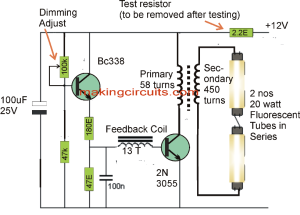
The straightforward circuit will probably illuminate up to two 20watt fluoroscent tubes from a 12v supply.
The circuit also offers a brightness change to minimize the current through the battery pack.
The two counterparts equally offer the illumination part taken off and the 100uF eliminated. elimination of the 100uF minimizes the illumination collectively decreases the current from 500mA to 250mA to produce a extremely productive circuit for an unexpected emergency circumstance.
Note: Illuminating a 20 watt tube (regular 2-foot tube) delivers much-more brightness than the usual 5 watt CFL.


This particular 20 watt, 5 watt Fluorescent Lamp Inverter circuit will probably push a 5 watt tube from an old CFL lamp from 6v or 12v. It creates an incredibly convenient emergency light.
The transformer is built by winding FIVE HUNDRED turns for the secondary section.
This includes turning around TEN turns on upper part of every other prior to progressing over the rod. The rod may be circular or chiseled, from your outdated AM radio. It is actually known as ferrite rod. The FIVE HUNDRED turns must be put in prior to achieving the finish which implies ONE HUNDRED turns should consume 1/5th of the range. This lowers the voltage amongst the turns since the enamel is only going to endure ONE HUNDRED volts.
Prior to starting turning, employ a minimum of 3 levels of “sticky-tape” in order to avoid the high voltage shorting into the rod.
The dimensions of the wire is not really crucial and nearly anything around 0.25mm or finer will probably be acceptable. Following winding the secondary, the primary can be FIFTY turns plus the feedback will be TEN turns.
The primary might be 0.5mm wire and also the feedback 0.25mm.
Link up the transistor, parts and tube and switch the circuit ON rather quickly, and OFF. In case the tube fails to light up right away, invert the wires to the feedback winding.
The transistor has to be 2N 3055 (or perhaps the plastic-type variation, TIP 3055). It is going to get heated while lighting the light fixture and must be mounted on a heatsink. The lamp ought not to be extracted as the circuit could overload and harm the transistor.
The proposed emergency Fluorescent Lamp Inverter circuit requires 250mA while operating a 5 watt CFL (or 18 watt fluorescent conduit) on 12v supply. The 1k base resistor could be lowered to 820R and the illumination increases marginally however the current increases to 500mA.
The circuit is much efficient on 6v. The 1k base resistor is lowered to 220R and the transistor continues to be cool.
Hindi Translation
सीधा सर्किट शायद एक 12 वी की आपूर्ति से दो 20Watt fluoroscent ट्यूबों के लिए ऊपर रोशन करेंगे।
सर्किट भी बैटरी पैक के माध्यम से वर्तमान को कम से कम करने के लिए एक चमक परिवर्तन प्रदान करता है।
दो समकक्षों के समान रूप से दूर ले जाया रोशनी हिस्सा और सफाया 100uF प्रदान करते हैं। 100uF के उन्मूलन रोशनी सामूहिक रूप से एक अप्रत्याशित आपातकालीन परिस्थिति के लिए एक अत्यंत उत्पादक सर्किट के उत्पादन के लिए 250mA को 500mA से वर्तमान कम हो जाती है कम करता है।
नोट: एक 20 वाट ट्यूब (नियमित रूप से 2 फुट ट्यूब) रोशन सामान्य 5 वाट सीएफएल की तुलना में काफी अधिक चमक बचाता है।
20 वाट सीएफएल पलटनेवाला सर्किट सीएफएल
यह विशेष रूप से 20 वाट, 5 वाट फ्लोरोसेंट लैंप इन्वर्टर सर्किट शायद 6V से एक पुराने सीएफएल लैंप से एक 5 वाट ट्यूब धक्का या 12 वी जाएगा। यह एक अविश्वसनीय रूप से सुविधाजनक इमरजेंसी लाइट बनाता है।
ट्रांसफॉर्मर माध्यमिक अनुभाग के लिए पाँच सौ से बदल जाता है घुमावदार द्वारा बनाया गया है।
यह हर दूसरे से पहले छड़ी पर प्रगति करने के ऊपरी भाग पर लगभग दस बदल जाता मोड़ भी शामिल है। रॉड परिपत्र या अपनी पुरानी AM रेडियो से, गढ़े हुए हो सकता है। यह वास्तव में फेराइट छड़ी के रूप में जाना जाता है। पांच सौ से बदल जाता रेंज के 1/5 वीं का उपभोग करना चाहिए एक सौ से बदल जाता है जो अर्थ खत्म प्राप्त करने के लिए पूर्व में डाल दिया जाना चाहिए। यह तामचीनी केवल एक सौ वोल्ट सहना जा रहा है के बाद से बदल जाता है के बीच वोल्टेज कम करती है।
मोड़ शुरू करने से पहले, रॉड में shorting उच्च वोल्टेज से बचने के क्रम में "चिपचिपा टेप" के 3 स्तरों की एक न्यूनतम रोजगार।
तार के आयामों वास्तव में महत्वपूर्ण है और 0.25 मिमी या महीन भर के लगभग कुछ भी शायद स्वीकार्य हो जाएगा नहीं है। माध्यमिक घुमावदार के बाद, प्राथमिक पचास बदल जाता है हो सकता है प्लस प्रतिक्रिया दस बदल जाता है हो जाएगा।
प्राथमिक 0.5 मिमी तार और भी प्रतिक्रिया 0.25 मिमी हो सकता है।
ट्रांजिस्टर, भागों और ट्यूब लिंक अप और नहीं बल्कि जल्दी पर सर्किट स्विच। मामले में ट्यूब, अभी तक प्रकाश घुमावदार प्रतिक्रिया के लिए तारों पलटना विफल रहता है।
ट्रांजिस्टर 3055 (या शायद प्लास्टिक-प्रकार की भिन्नता, टिप 3055) 2N हो गया है। यह प्रकाश स्थिरता प्रकाश व्यवस्था, जबकि गरम हो जा रहा है और एक heatsink पर मुहिम शुरू की जानी चाहिए। दीपक अधिभार और ट्रांजिस्टर को नुकसान पहुँचा सकता सर्किट के रूप में निकाला नहीं होना चाहिए।
12 वी की आपूर्ति पर एक 5 वाट सीएफएल (या 18 वाट फ्लोरोसेंट नाली) जबकि संचालन प्रस्तावित आपातकालीन फ्लोरोसेंट लैंप इन्वर्टर सर्किट 250mA की आवश्यकता है। 1K आधार रोकनेवाला 820R के लिए उतारा जा सकता है और 500mA करने के लिए रोशनी बढ़ जाती मामूली हालांकि वर्तमान बढ़ जाती है।
सर्किट 6V पर बहुत ही कुशल है। 1K आधार रोकनेवाला 220R के लिए उतारा जाता है और ट्रांजिस्टर शांत होना जारी है।
Leave a Reply