An automatic battery bank charger circuit with an automatic overcharge cut-off function for use with an electric vehicle is described in the post. Mr. Sergey asked for the suggestion.
Circuit Parameters and Description
My name is Sergey, and I'm from UK. I'm attempting to convert a little automobile to an electric vehicle.
The lithium battery modules that make up the whole pack are configured in the accompanying PDF.
You might be able to recommend a battery charger or setup that I could use to charge the pack.
I have either 240 or 415 volts of AC accessible.
Battery Wiring Details
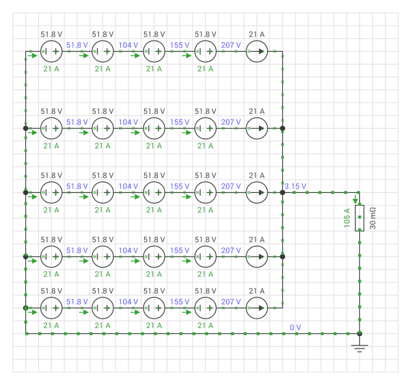
The Circuit layout
The Li-ion battery setup in series and parallel mode, as seen in the above image, can provide an enormous 210V at about 80 Amps.
In order to effectively charge this rather large battery configuration, we must have a controller that can regulate current and provide the pack with the necessary voltage.
Since the 240V AC supply appears more suitable, it may be utilized as the input for the aforementioned function.
The suggested 220V Li-ion Battery Module charger circuit is depicted in the accompanying figure. Let's examine how it operates in more depth using the following description:
Circuit Diagram

Circuit Functioning
So let us learn deeply how this circuit works. It is actually pretty similar to one of the earlier designs we talked about for a high-voltage battery charger. The main difference here is that instead of using a relay we have swapped it out for a thyristor and we have also added a high-voltage dropping capacitor to keep things safe
Now when it comes to the mains high current it gets nicely reduced thanks to the reactance of that 100uF/400V non-polar capacitor. This brings it down to around 5 amps which then gets fed into the battery bank through the thyristor we mentioned. If you want to pump up that current even more all you need to do is increase the capacitance of that 100uF/400V capacitor
In this setup the thyristor or SCR as some folks call it acts like a switch It stays in the ON position as long as the BC547 transistor at its gate is kept OFF. You can see that the base of the BC547 is connected to an op-amp output that is set up as a comparator
As long as the op-amp’s output is low the BC547 remains OFF which keeps the thyristor ON This whole situation continues as long as the voltage at pin #3 of our IC which is sensing input stays below the reference voltage at pin #2
Now since pin #3 is connected to the positive side of the battery via a resistive network it means that we need to adjust that 10K preset resistor at pin #3 so that when the battery is fully charged the voltage there just barely exceeds what is fixed at pin #2
Once that happens the op-amp's output at pin #6 flips from low to high almost instantly. This action turns ON the BC547 and switches OFF the thyristor which stops the battery charging right then and there
Function of Hysteresis Resistor
Now let us talk about that hysteresis resistor Rx which is connected between pin #6 and pin #3 of our IC. This little guy makes sure that once the op-amp switches ON it stays in that position for a bit until the battery voltage drops down to a certain lower threshold level
When it hits this lower level which is not safe the op-amp changes again and kicks off the charging process by sending a logic low signal out from its output at pin #6
The difference between where we cut off charging when fully charged and where we start charging again when low is actually proportional to how much Rx is set. You might need to play around with it a bit to find just the right value If you use higher values for Rx you will get smaller differences and if you go lower you will see bigger differences
Also there is a potential divider network made up of those 220K and 15K resistors. This setup ensures that we get just the right amount of voltage dropped down for op-amp pin #3 nothing too high for it to handle
The operating voltage for our op-amp at pin #7 comes from a BJT emitter follower configuration that is hooked up across one of the end batteries connected to the negative line of our battery pack
If you have any questions about this 220V Li-Ion battery bank charger circuit or anything else related do not hesitate to drop your thoughts in the comment box below.
A Word of Caution
WARNING The design I just explained is not isolated from the AC mains line which means it can be super dangerous if you touch it while it is switched on Please be very careful
Leave a Reply