• Skip to main content
  • Skip to primary sidebar

Making Easy Circuits

Learn and build electronic circuits

You are here: Home / Voltage Regulators / 3V to 12V Transistor Boost Converter Circuit

3V to 12V Transistor Boost Converter Circuit

Last Updated on June 29, 2018 by Admin 6 Comments

The following article will teach you how to build a simple transistorized boost converter circuit which will allow the user to acquire 12V from a 3V source very easily.

Introduction

If you have been wondering how to boost a small 3V battery voltage to a significantly large 12V output, then this article can be very useful for you, which you can build and use it for the mentioned purpose.

With this circuit you will be now able to apply a controlled boosted voltage and illuminate bigger LEDs rated to operate at 12V, with a 3V supply inputs.

How the Boost Converter Works

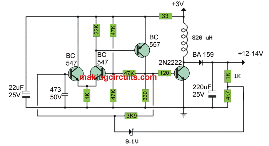
As can be seen the schematic below the proposed 3V to 12v boost converter circuit utilizes just a few transistors, an inductor and some capacitor to enable a full fledged 12V to be acquired from a minimal 3V supply input.

Within this tiny switching power supply, a Schmitt trigger oscillator is utilized to stimulate a switching transistor which supplies current into a compact inductor.

Power is trapped in the inductor as the transistor is switched on, and unveiled on the load circuit as soon as the transistor reboots.

Higher or lower voltages can be acquired through altering the voltage divider which feeds the zener diode. The performance is approximately 80% by using a higher Q inductor.

The output voltage will depend on the load resistance and is particularly restricted to a zener diode which puts a stop to the oscillator once the voltage gets to about 14 volts.

3V to 12V Transistor Boost Converter Circuit


You'll also like:

  • 1.  12V to 24V Voltage Doubler Circuit using IC 4093
  • 2.  Customizable Fixed Voltage Regulator Circuit using Opamp
  • 3.  Zero Crossing Detector Circuit
  • 4.  Electronic Fuse Circuit for Power Supply  
  • 5.  1.25 V to 30 V Variable Power Supply Circuit using IC LM350
  • 6.  3V to 5V Boost Circuit for Battery Charging and LED Driver Applications

About Admin

Hey friends, Thanks a bunch for stopping by this site! I am an engineer with a Bachelor of Engineering in Electronics and Telecommunication. One of my passions is gathering information from all sorts of electronics books and tutorials. I then take that information and compile it into a language that is super easy to understand. My goal is to make those complex electronics circuit concepts and technical terms much more accessible for all the new and budding electronics engineers out there. I can also design customized circuit diagrams as required by the users.
If you have any questions related to this field, please do not hesitate to drop a comment! I am always here and ready to help you out with any queries you might have. I cannot wait to hear from you!

Reader Interactions

Comments

  1. Odur Emmanuel Gomich says

    April 15, 2022 at 6:47 pm

    So good

    Reply
  2. JOHN CHEN says

    February 3, 2021 at 12:06 pm

    Very nice. I like the pwm. I’m working on a 555 driving a mosfet to boost 12v to 30v. The cv pin does pwm.

    Reply
  3. Yusuf Abiodun says

    May 21, 2018 at 3:33 pm

    Good day and Thank you. The resistors in the 3v to 12v boost converter were not labelled and cannot be uploaded. Thanks.

    Reply
  4. Yusuf Abiodun says

    May 21, 2018 at 3:32 pm

    Good day and Thank you. The resistors in the 3v to 12v boost converter were not labelled. Thanks.

    Reply
    • admin says

      May 23, 2018 at 9:04 pm

      Thank you! but you don’t need to download the image, you can simply right click on the image and save it in your computer. Part numbers are all given in the diagram itself

      Reply
  5. Yusuf Abiodun says

    May 21, 2018 at 2:01 am

    Good work, but the circuit diagram cannot be up-loaded thanks, the parts are not listed. Thanks,

    Reply

Leave a Reply Cancel reply

Your email address will not be published. Required fields are marked *

Primary Sidebar

Categories

  • 3 Phase (4)
  • 8051 Microcontroller (1)
  • Arduino (11)
  • Audio and Amplifier (102)
  • Automation (8)
  • Battery Chargers (64)
  • Bicycle Projects (4)
  • Car and Motorcycle Projects (39)
  • Datasheets (10)
  • DIY Projects (5)
  • Electrical (15)
  • Free Energy (6)
  • Games Projects (2)
  • High Voltage (14)
  • Hobby Projects (30)
  • Household Circuits (2)
  • IC 555 Circuits (5)
  • Ignition Circuits (2)
  • Indicators (50)
  • Infrared (6)
  • Inverter Circuits (29)
  • Lights and Lamps (97)
  • Medical (8)
  • Meter and Tester Circuits (38)
  • Motor Driver (17)
  • New Circuits (56)
  • Oscillators (30)
  • Pets and Pests (5)
  • Power supply (80)
  • Protection Circuits (25)
  • PWM (9)
  • Remote Control (20)
  • Security and Alarm Circuit (48)
  • Sensors and Detectors (66)
  • Signal Processor (23)
  • Solar Controller Circuits (62)
  • SSR (3)
  • Temperature Controller (20)
  • Timer (25)
  • Transformerless (7)
  • Transmitters (12)
  • Tutorials (45)
  • UPS (2)
  • Voltage Regulators (57)
  • Water Sensor and Controller (29)
  • Home
  • Privacy Policy
  • Contact
  • Disclaimer
  • Copyright

© 2025 · Making Easy Circuits