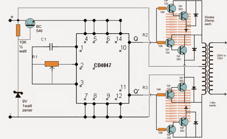
The submit describes a very simple 48V inverter circuit which can be calculated at as high as 2 KVA. The whole design is designed around a single IC 4047 and a few power transistors.

Talking about the demonstrated 48V inverter circuit, the IC 4047 forms the main oscillator stage accountable of generating a totem pole outputs for the linked output stage.
The output stage is created by configuring a 4 individual high gain high power transistors modules, two of them on each channel of the push pull output stage.
The TIP122 are on their own internally set up as Darlingtons that happen to be furthermore associated with TIP35 transistor in the Darlington for producing especially strong current gain across each of the components.
C1 and R1 has to be properly set for attaining the preferred frequency as per the needed requirements...could be 50 Hz or 60 Hz.
The presented 48 V inverter configuration is made to produce an enormous 2 kva of output power offered the devices are installed on sufficiently large heatsinks and the battery rated at 48 V, 100 AH, also the transformer rated at 36-0-36V, 1 kva
For lower outputs, certainly one of the modules could possibly be eradicated from each of the channels.
The BJT BC546 is placed to offer a fairly fixed 9 V to the IC to be able to maintain the IC safe from the high battery voltage and within its specific working voltage limit.
Leave a Reply