• Skip to main content
  • Skip to primary sidebar

Making Easy Circuits

Learn and build electronic circuits

You are here: Home / Signal Processor / 555 Timer Ramp Generator

555 Timer Ramp Generator

Last Updated on January 10, 2018 by Admin Leave a Comment

The post explains how a IC 555 timer ramp generator circuit can be made using a single IC 555 and few other passive components

When a capacitor gets charged from the source of voltage via resistor, the capacitor generates high waveform. The charging of the capacitor from a fixed source of current also generates ramp. This project is based on the said foundation. Following is a circuit diagram of ramp circuit generator using 555 timer. In this diagram, the resistor in the circuit is alternated with a PNP transistor. Using PNP enables producing constant current charge.

555 ramp generator circuit


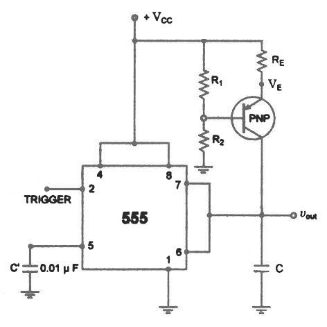
The current charge with the help of PNP is signified as:
ic = VCC – VE / RE
where VE = R2 / (R1 + R2) *VCC + VBE

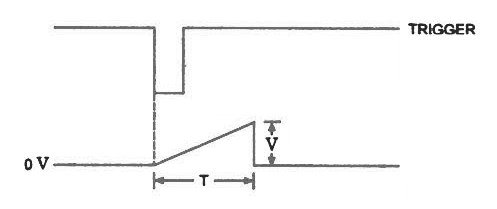
When a trigger starts the monostable multivbrator as shown in figure, the PNP current source forces a constant charging into the capacitor C. The voltage across the capacitor is, therefore, a ramp as illustrated in the figure. The slope of the ramp is given as

When 555 monostable multi-vibrator timer is enabled, the source of current from the PNP pushes to charge constantly to C Capacitor. Therefore, the voltage available in the capacitor is a ramp [as shown in Fig 1.0].

Slope, s = I/C

The following image shows the waveform of the slope of the IC 555 ramp generator circuit

ramp trigger and waveform


You'll also like:

  • 1.  Semiconductor Diodes – Internal Structure and Working Explained
  • 2.  Simple Transistor Latching Circuit Explained
  • 3.  Dog Barking Sound Simulator Circuit
  • 4.  3 Phase Signal Generator Circuit
  • 5.  Sine Wave Oscillator Circuit
  • 6.  Relay Function Explained – How to Wire N/O and N/C Terminals

About Admin

Hey friends, Thanks a bunch for stopping by this site! I am an engineer with a Bachelor of Engineering in Electronics and Telecommunication. One of my passions is gathering information from all sorts of electronics books and tutorials. I then take that information and compile it into a language that is super easy to understand. My goal is to make those complex electronics circuit concepts and technical terms much more accessible for all the new and budding electronics engineers out there. I can also design customized circuit diagrams as required by the users.
If you have any questions related to this field, please do not hesitate to drop a comment! I am always here and ready to help you out with any queries you might have. I cannot wait to hear from you!

Reader Interactions

Leave a Reply Cancel reply

Your email address will not be published. Required fields are marked *

Primary Sidebar

Categories

  • 3 Phase (4)
  • 8051 Microcontroller (1)
  • Arduino (11)
  • Audio and Amplifier (102)
  • Automation (8)
  • Battery Chargers (64)
  • Bicycle Projects (4)
  • Car and Motorcycle Projects (39)
  • Datasheets (10)
  • DIY Projects (5)
  • Electrical (15)
  • Free Energy (6)
  • Games Projects (2)
  • High Voltage (14)
  • Hobby Projects (30)
  • Household Circuits (2)
  • IC 555 Circuits (5)
  • Ignition Circuits (2)
  • Indicators (50)
  • Infrared (6)
  • Inverter Circuits (29)
  • Lights and Lamps (97)
  • Medical (8)
  • Meter and Tester Circuits (38)
  • Motor Driver (17)
  • New Circuits (56)
  • Oscillators (30)
  • Pets and Pests (5)
  • Power supply (80)
  • Protection Circuits (25)
  • PWM (9)
  • Remote Control (20)
  • Security and Alarm Circuit (48)
  • Sensors and Detectors (66)
  • Signal Processor (23)
  • Solar Controller Circuits (62)
  • SSR (3)
  • Temperature Controller (20)
  • Timer (25)
  • Transformerless (7)
  • Transmitters (12)
  • Tutorials (45)
  • UPS (2)
  • Voltage Regulators (57)
  • Water Sensor and Controller (29)
  • Home
  • Privacy Policy
  • Contact
  • Disclaimer
  • Copyright

© 2025 · Making Easy Circuits