In this post I have discussed an LED chaser circuit diagram which will sequentially light up 8 LED one after the other until all the 8 LEDs are illuminated and shut off the all the LEDs and then repeat the process continually.
Circuit Description
So looking at our schematic we have got a low-frequency astable oscillator circuit. We have built it using two gates IC1a and IC1b which come from the IC 4011 quad two-input NAND gate. Now the speed at which this astable oscillator does its thing—its operating frequency—is all down to the values of C1 and R11.
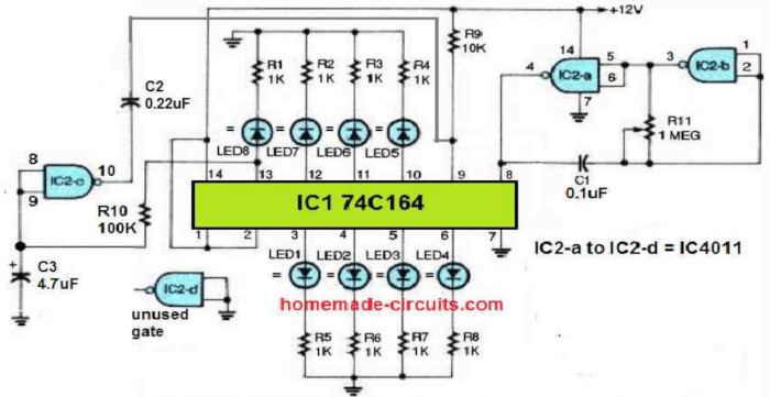
This setup works really well to generate those clock pulses we need to feed into the IC1's 74C164 shift register. Basically the positive output pulses from the clock which we find at pin 4 of IC2 get sent right into the shift register's clock input at pin 8 of IC1.
Now each of the shift register's outputs is hooked up to an LED. And to make sure we do not fry those LEDs, each one is connected in series with a 1K resistor to limit the current.
Here is where it gets a bit clever, the input of gate IC2c is connected to the eighth output of the shift register—that is at pin 13. But we have added a little twist: a time-delay RC configuration made up of R10 and C3.
The output of that gate then goes to the clear input of the shift register at pin 9, and it goes through a capacitor. So what happens is when the eighth clock pulse comes along then LED8 lights up and at the same time C3 starts charging up as soon as pin 13 of IC1 goes positive.
After a little bit of waiting, due to the RC delay, the output of IC2c goes low, and then that clears all the outputs of the shift register.
So what you see is the LEDs lighting up one after the other. LED1 turns on with the first clock pulse, LED2 with the second, and so on until all eight LEDs are shining bright.
Then that clear pulse from IC2c comes along and shuts off all the LEDs once the eighth one lights up. And then the whole thing starts all over again.
Now if you want to tweak how long LED8 stays on then you can play around with the values of R10 and C3. You can adjust those values to make LED8 stay on for the exact same amount of time as all the other LEDs.
And if you are looking to speed up or slow down the whole sequence then it is all about that RC time delay circuit. To make the sequence faster you need a smaller RC time delay; and to slow it down, you need a larger one.
So if you increase the value of either R10 or C3 then that will actually shorten the delay period. And if you decrease their values then you will extend the delay time.
Parts List
| Part | Description | Quantity |
|---|---|---|
| IC1 | 74C164 | 1 |
| IC2 | IC4011 (IC2-a to IC2-d) | 1 |
| R1 | 1K Ohm | 1 |
| R2 | 1K Ohm | 1 |
| R3 | 1K Ohm | 1 |
| R4 | 1K Ohm | 1 |
| R5 | 1K Ohm | 1 |
| R6 | 1K Ohm | 1 |
| R7 | 1K Ohm | 1 |
| R8 | 1K Ohm | 1 |
| R9 | 10K Ohm | 1 |
| R10 | 100K Ohm | 1 |
| R11 | 1 Meg Ohm | 1 |
| C1 | 0.1uF | 1 |
| C2 | 0.22uF | 1 |
| C3 | 4.7uF | 1 |
| LED1 | LED | 1 |
| LED2 | LED | 1 |
| LED3 | LED | 1 |
| LED4 | LED | 1 |
| LED5 | LED | 1 |
| LED6 | LED | 1 |
| LED7 | LED | 1 |
| LED8 | LED | 1 |
Leave a Reply