• Skip to main content
  • Skip to primary sidebar

Making Easy Circuits

Learn and build electronic circuits

You are here: Home / Sensors and Detectors / AC Mains Current Detector Circuit

AC Mains Current Detector Circuit

Last Updated on January 4, 2021 by Admin 2 Comments

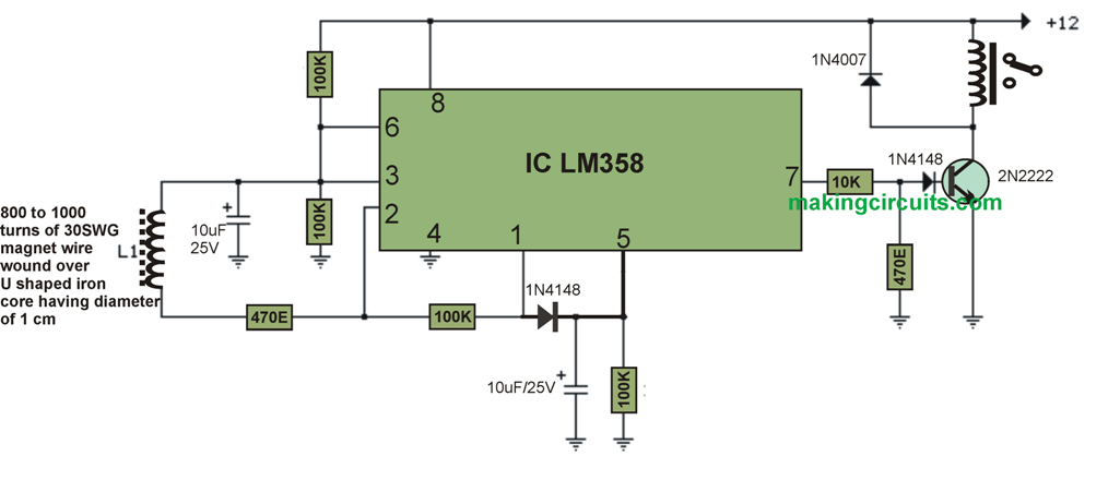
This AC mains current detector circuit identifies current levels within one of the AC mains supplies with the aid of an inductive pickup sensor (L1) made using a one inch diameter U-bolt wrapped with eight hundred spins of 30 SWG super enameled wire.

It senses AC mains line currents of approximately 200 mA or maybe more without requiring any specific electrical connectivity to the supply. The sensing could possibly be composed of different iron variety rings or transformer cores allowing you adequate room to cross any of the AC lines via the core.

Just one of the current bearing lines, possibly the phase or the neutral need to be positioned via the central part of the sensor to steer clear of the magnetic flux cancelling.

I certified the proposed AC mains current circuit working with a a couple of cable prolongation which I had set apart the double wires a tiny length with a multi tool to enable the U-bolt to encircle just one cable.

The magnetic pick-up sensor (U-bolt) generates approximately 4 millivolts maximum for a AC mains line current of 250 mA, or AC load of close to thirty watts.

The transmission from the sensor is enhanced roughly two hundred times at the end result of the op-amp pin 1 that may be consequently peak determined by the capacitor and diode connected to pin 1. The 2nd op-amp is used within the IC as a comparator which picks up a voltage increase more than the diode drop.

The minimal transmission necessary to bring about the comparator stage output to turn positive is approximately 800 mV maximum which amounts to roughly a 30 watt load on the Alternating current line.

The output of 1458 op-amp is only going to fluctuate within a few volts of negative hence a voltage divider (1K/470) is employed to bring down the no-signal voltage to approximately 0.7 volts.

A supplementary diode is inserted range with the transistor base to guarantee it switches off the minute the op-amp voltage is 2 volts. You can receive a small amount of relay stuttering in case the AC load is adjacent to the changing over level as a result a more substantial load of 50 watts or even more strongly suggested.

The level of responsiveness of this AC mains current circuit may very well be augmented by contributing more number of turns to the pickup coil.

AC mains line current circuit

You'll also like:

  • 1.  Carbon Gauge Circuit
  • 2.  Current Detector Circuit on PCB Tracks
  • 3.  Simple PIR Water Sprinkler Circuit
  • 4.  Piezo Driver Circuit with LED Warning Indicator
  • 5.  Under Soil Gold Detector Circuit
  • 6.  How to Build a Insect Wing Signal Detector Circuit

About Admin

Hey friends, Thanks a bunch for stopping by this site! I am an engineer with a Bachelor of Engineering in Electronics and Telecommunication. One of my passions is gathering information from all sorts of electronics books and tutorials. I then take that information and compile it into a language that is super easy to understand. My goal is to make those complex electronics circuit concepts and technical terms much more accessible for all the new and budding electronics engineers out there. I can also design customized circuit diagrams as required by the users.
If you have any questions related to this field, please do not hesitate to drop a comment! I am always here and ready to help you out with any queries you might have. I cannot wait to hear from you!

Reader Interactions

Comments

  1. Mark says

    December 29, 2020 at 5:48 pm

    Hello Admin,

    Thank you for sharing this circuit!

    Would it be possible for you to make a re-settable fuse based on this? I’m hoping for something with adjustable current cut-off in the range of 1 amp to 10 amps.

    This will be useful when troubleshooting or testing appliances like microwave ovens that blow fuse, for example.

    Thank you.

    Reply
    • admin says

      January 4, 2021 at 4:01 pm

      Hello Mark, do you want the the circuit to latch and switch OFF in response to a current, which can be then reset manually?

      Reply

Leave a Reply Cancel reply

Your email address will not be published. Required fields are marked *

Primary Sidebar

Categories

  • 3 Phase (4)
  • 8051 Microcontroller (1)
  • Arduino (11)
  • Audio and Amplifier (102)
  • Automation (8)
  • Battery Chargers (64)
  • Bicycle Projects (4)
  • Car and Motorcycle Projects (39)
  • Datasheets (10)
  • DIY Projects (5)
  • Electrical (15)
  • Free Energy (6)
  • Games Projects (2)
  • High Voltage (14)
  • Hobby Projects (30)
  • Household Circuits (2)
  • IC 555 Circuits (5)
  • Ignition Circuits (2)
  • Indicators (50)
  • Infrared (6)
  • Inverter Circuits (29)
  • Lights and Lamps (97)
  • Medical (8)
  • Meter and Tester Circuits (38)
  • Motor Driver (17)
  • New Circuits (56)
  • Oscillators (30)
  • Pets and Pests (5)
  • Power supply (80)
  • Protection Circuits (25)
  • PWM (9)
  • Remote Control (20)
  • Security and Alarm Circuit (48)
  • Sensors and Detectors (66)
  • Signal Processor (23)
  • Solar Controller Circuits (62)
  • SSR (3)
  • Temperature Controller (20)
  • Timer (25)
  • Transformerless (7)
  • Transmitters (12)
  • Tutorials (45)
  • UPS (2)
  • Voltage Regulators (57)
  • Water Sensor and Controller (29)
  • Home
  • Privacy Policy
  • Contact
  • Disclaimer
  • Copyright

© 2025 · Making Easy Circuits