• Skip to main content
  • Skip to primary sidebar

Making Easy Circuits

Learn and build electronic circuits

You are here: Home / Car and Motorcycle Projects / Adding a Buzzer to Car Indicator Circuit

Adding a Buzzer to Car Indicator Circuit

Last Updated on November 24, 2018 by Admin Leave a Comment

Whenever the left or right directional blinker lights come on in a car, it is almost always the situation that happens prior to taking a turn, through a little movement of the steering wheel. These turn lights happen to be deactivated well before time, without the motorist knowing. This kind of scenario could possibly create a major accident because other vehicles that may be just behind does not have any means of becoming alert to slow down.

Additionally, it usually transpires that the driver initiates the parking lights, turn off the car and move out, allowing these to be ON unintentionally, and slowly discharging away the car's battery.

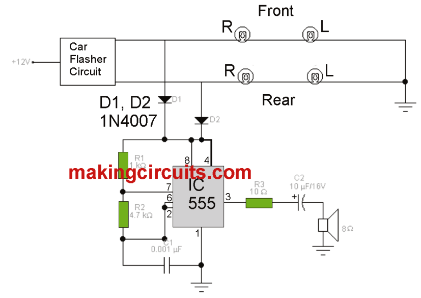
These types of complications could be solved with an ideal device that comes ON immediately with the activation of the lights. In the circuit here we are able to see a tiny oscillator that is in charge of producing an audible tone every time the turn indicator lamps or parking lights are switched on.

The oscillator is founded on the integrated circuit 555. The frequency of the audio could be altered via the resistors R1 and R2 and the capacitor C1. The diodes D1 and D2 tend to be of great significance, given that they accomplish the functionality of a valve system to avoid the current from entering the other lights just in case you only want to switch on one side lamps.

buzzer circuit for car turn flasher

You'll also like:

  • 1.  Simple Vehicle Immobilizer Circuit
  • 2.  How to Make a Solar E Rickshaw Circuit at Home
  • 3.  DIY GSM Car Security Alarm Circuit
  • 4.  Enhance Car DRL with this Circuit
  • 5.  Simple Line Follower Circuit
  • 6.  Making Smart Car Turn-Signals, Side-Markers, and Parking Lights

About Admin

Hey friends, Thanks a bunch for stopping by this site! I am an engineer with a Bachelor of Engineering in Electronics and Telecommunication. One of my passions is gathering information from all sorts of electronics books and tutorials. I then take that information and compile it into a language that is super easy to understand. My goal is to make those complex electronics circuit concepts and technical terms much more accessible for all the new and budding electronics engineers out there. I can also design customized circuit diagrams as required by the users.
If you have any questions related to this field, please do not hesitate to drop a comment! I am always here and ready to help you out with any queries you might have. I cannot wait to hear from you!

Reader Interactions

Leave a Reply Cancel reply

Your email address will not be published. Required fields are marked *

Primary Sidebar

Categories

  • 3 Phase (4)
  • 8051 Microcontroller (1)
  • Arduino (11)
  • Audio and Amplifier (102)
  • Automation (8)
  • Battery Chargers (64)
  • Bicycle Projects (4)
  • Car and Motorcycle Projects (39)
  • Datasheets (10)
  • DIY Projects (5)
  • Electrical (15)
  • Free Energy (6)
  • Games Projects (2)
  • High Voltage (14)
  • Hobby Projects (30)
  • Household Circuits (2)
  • IC 555 Circuits (4)
  • Ignition Circuits (2)
  • Indicators (50)
  • Infrared (6)
  • Inverter Circuits (29)
  • Lights and Lamps (97)
  • Medical (8)
  • Meter and Tester Circuits (38)
  • Motor Driver (17)
  • New Circuits (56)
  • Oscillators (30)
  • Pets and Pests (5)
  • Power supply (81)
  • Protection Circuits (25)
  • PWM (8)
  • Remote Control (20)
  • Security and Alarm Circuit (48)
  • Sensors and Detectors (66)
  • Signal Processor (23)
  • Solar Controller Circuits (61)
  • SSR (3)
  • Temperature Controller (20)
  • Timer (25)
  • Transformerless (7)
  • Transmitters (12)
  • Tutorials (45)
  • UPS (2)
  • Voltage Regulators (57)
  • Water Sensor and Controller (29)
  • Home
  • Privacy Policy
  • Contact
  • Disclaimer
  • Copyright

© 2025 · Making Easy Circuits