In this post we discuss a couple of useful RF antenna signal booster circuits, which can be used with any RF receiver circuit to amplify incoming signals to higher levels, thereby enabling the use of smaller antenna, instead of long wire antennas.
As seen in Figure 1, a short pull-up antenna that occupies a high output impedance couples it to the low input impedance side of the receiver via a two-transistor impedance pairing network.

A good short antenna is made up from the transistor Q1’s high input impedance and high-frequency characteristics. Meanwhile, Q2’s low output impedance almost fits the receiver’s input.
This type of impedance-matching circuit permits an extensive range of frequencies from under 100 kHz to more than 30 MHz to enter the receiver.
Although the circuit doesn’t produce any voltage gain, the receiver’s performance is significantly improved.
Only when the signal reaching the antenna is strong, the matching circuit will ramp the receiver’s performance.
When there is no expected signal at the antenna, producing a working signal at the receiver is out of question.
Power Supply
When you contain the antenna signal booster circuit in a metal enclosure and use an internal 9 V battery, you get the best low-noise performance for the matching circuit.
Alternatively, an evenly-filtered noise-free external AC power source can be implemented as well as power supplied from the receiver, if any.
Just simple construction on a breadboard or perfboard with push-pins is more than enough for this circuit.
What you need to do is to keep all the leads short and practice a neat circuit building plan. You may use any type of pull-up antenna after considering the space available for it.
Parts List
Q1 = MPF102, general-purpose, N-channel FET
Q2 = 2N3904, general-purpose, NPN silicon transistor
R1 = 1.5-megohm, 1/4 -watt, 5% resistor
R2, R5 = 1000-ohm, 1/4 -watt, 5% resistor
R3, R4 = 27,000-ohm. 1/4 -watt. 5%resistor
C1 = 680pE ceramic-disc capacitor
C2 = 0.01pF ceramic-disc capacitor
C3, C4 = 0.1pf, ceramic-disc capacitor
C5 = 470pF I6-WVDC, electrolytic
capacitor
S1—SPST toggle switch
Signal Booster Circuit
A simple antenna signal booster circuit as depicted in Figure 2 will do the trick if your receiver requires a higher level RF-input signal than what the matching network can produce.
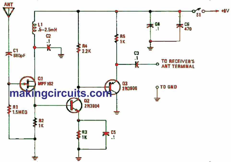
The antenna signal booster circuit is constructed around a few transistors and supplementing components.
Due to that, the circuit delivers an RF gain of around 12 to 18 dB from a source of 100 kHz to more than 30 MHz, complementing the schematic in Figure 1.
The RF signal is directly attached from the Q1’s source terminal to the base of Q2.
This side is preset as a voltage amplifier. The output of Q2 is coupled directly to the base of Q3 which is configured as an emitter-follower amplifier.
Furthermore, Q3 functions to check and isolate the gain stage from receiver side of the RF-input circuitry.
To attenuate the sound of the power source from reaching the FET (Q1), inductor L1 is introduced.
You may any RF choke values from 0.5 to 2.5 mH. Then, the value of R2 triggers the bias for Q2 to around 2 V. If you found the voltage is below 2 V, you must increase R2’s value to 1.5k ohms.
Finally, to dip deeper than 100 kHz to the bottom of the RF spectrum, you must increase C1 to 0.002 µF.
Parts List
Q1 = MPF102. general-purpose.N-channel FET
Q2 = 2N3904
Q3 = 2N3906
R1 = 1.5M1/4 -watt. 5% resistor
R2, R3, R5 = 1k, 1/4 -watt. 5%resistor
R4 = 2.2k. 1/4 -watt. 5% resistor
C1 = 680pF ceramic-disc capacitor
C2-C5 = 0.1uF. ceramic-disc capacitor
C6 = 470uF/16-WVDC. electrolytic capacitor
L1 = 0.5-2.5-mH RF choke
S1 = SPST toggle switch
We want a mobile phone network booster circuit
I will try to get it soon, and let you know….
Very informativo, WILL try it.
I WANT TO increase MY list db cause I WILL use a 25mt Long lm400 cable, any idea.
Ok great thanks!