• Skip to main content
  • Skip to primary sidebar

Making Easy Circuits

Learn and build electronic circuits

You are here: Home / Arduino / Arduino 2-Step Programmable Timer Circuit

Arduino 2-Step Programmable Timer Circuit

Last Updated on May 28, 2025 by Admin Leave a Comment

The following article explains methods to create a basic 2-step Arduino programmable timer circuit that can be used to separately alter the ON and OFF timings of an electrical load.

You may easily do this by making a small change to the program code, for instance, if you want a light to stay ON for 24 hours and OFF for 2 hours. Similarly, by altering the code suitably, you may change the output timings to any other desired set of time intervals.

To begin the timer function in accordance with your particular application requirements, simply build and upload the following code to your Arduino board.

Program Code

void setup(){
pinMode(13, OUTPUT);
}
void loop(){

digitalWrite(13, HIGH);
delay(86400000);
digitalWrite(13, LOW);
delay(3600000);
}

The output ON and OFF delay time intervals, in milliseconds, are determined by the lines delay(86400000); and delay(3600000); in the sample code above. In this case, 3600000 shows a one-hour delay, whereas 86400000 milliseconds represents 24 hours.

To obtain the necessary output delays, you can alter these two variables to suit your preferences.

The Arduino will keep on alternating between the two-step ON/OFF timing cycle soon after it has been configured and switched on, as long as the system continues to get power.
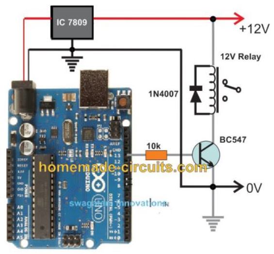
Circuit Diagram

The following diagram shows the entire circuit schematic as well as the Arduino links:

Arduino programmable timer circuit

Creating an Arduino One-Shot Timer Circuit

The code listed below can be used if you want the timer to be a one-shot kind that will turn off forever after the predetermined delay rather than looping over the two-step timer:

int led = 13; // Pin 13 has an LED connected on most Arduino boards.

unsigned long DELAY_TIME = 10000; // 10 sec
unsigned long delayStart = 0; // the time the delay started
bool delayRunning = false; // true if still waiting for delay to finish

void setup() {
pinMode(led, OUTPUT); // initialize the digital pin as an output.
digitalWrite(led, HIGH); // turn led on

// start delay
delayStart = millis();
delayRunning = true;
}

void loop() {
// check if delay has timed out
if (delayRunning && ((millis() - delayStart) >= DELAY_TIME)) {
delayRunning = false; // finished delay -- single shot, once only
digitalWrite(led, LOW); // turn led off
}
}

You may choose this circuit if you're looking for a discreetly constructed version of the same programmable timer circuit.

Bill of Materials for the Arduino Programmable Timer Circuit

  • Arduino UNO Board = 1
  • IC 7809 = 1
  • BC547 = 1
  • 1N4007 Diode = 1
  • 10k 1/4 w resistor = 1
  • Relay 12V/400 ohm/SPDT/5 amp = 1
  • 12V AC to DC Adapter = 1

You'll also like:

  • 1.  How to Make a Sinewave Inverter Circuit Using Arduino
  • 2.  Accurate 24 Hour Timer Circuit
  • 3.  Simple Egg Timer Circuit
  • 4.  Bedside Lamp Timer Circuit
  • 5.  1 Hour to 5 Hour Customizable Timer Circuit
  • 6.  How to Build a Reverse Forward Motor Timer Circuit for Incubator Mechanism

About Admin

Hey friends, Thanks a bunch for stopping by this site! I am an engineer with a Bachelor of Engineering in Electronics and Telecommunication. One of my passions is gathering information from all sorts of electronics books and tutorials. I then take that information and compile it into a language that is super easy to understand. My goal is to make those complex electronics circuit concepts and technical terms much more accessible for all the new and budding electronics engineers out there. I can also design customized circuit diagrams as required by the users.
If you have any questions related to this field, please do not hesitate to drop a comment! I am always here and ready to help you out with any queries you might have. I cannot wait to hear from you!

Reader Interactions

Leave a Reply Cancel reply

Your email address will not be published. Required fields are marked *

Primary Sidebar

Categories

  • 3 Phase (4)
  • 8051 Microcontroller (1)
  • Arduino (11)
  • Audio and Amplifier (102)
  • Automation (8)
  • Battery Chargers (64)
  • Bicycle Projects (4)
  • Car and Motorcycle Projects (39)
  • Datasheets (10)
  • DIY Projects (5)
  • Electrical (15)
  • Free Energy (6)
  • Games Projects (2)
  • High Voltage (14)
  • Hobby Projects (30)
  • Household Circuits (2)
  • IC 555 Circuits (4)
  • Ignition Circuits (2)
  • Indicators (50)
  • Infrared (6)
  • Inverter Circuits (29)
  • Lights and Lamps (97)
  • Medical (8)
  • Meter and Tester Circuits (38)
  • Motor Driver (17)
  • New Circuits (56)
  • Oscillators (30)
  • Pets and Pests (5)
  • Power supply (81)
  • Protection Circuits (25)
  • PWM (8)
  • Remote Control (20)
  • Security and Alarm Circuit (48)
  • Sensors and Detectors (66)
  • Signal Processor (23)
  • Solar Controller Circuits (61)
  • SSR (3)
  • Temperature Controller (20)
  • Timer (25)
  • Transformerless (7)
  • Transmitters (12)
  • Tutorials (45)
  • UPS (2)
  • Voltage Regulators (57)
  • Water Sensor and Controller (29)
  • Home
  • Privacy Policy
  • Contact
  • Disclaimer
  • Copyright

© 2025 · Making Easy Circuits