The Battery Low Voltage Alarm circuit has a very significant purpose aside from its basic design. It alerts you when a battery is about to run out so you can rush to the store and buy new cells before your device completely shuts down.
It is small and requires little current, therefore it may be included into gadgets in which the voltage has to be monitored.
When the battery's voltage begins to decline as it approaches the final stage of its useful life, the project's loud piezo buzzer produces a sound to notify you that the battery has been running out.
This is an easy-to-understand schematic of the suggested low battery alert circuit. A limited amount of easily obtainable components and a single CMOS integrated circuit are utilized.

Circuit Description
The voltage reference is produced by the combination of the resistor R1 and the zener diode ZD1.
It must be noted that, contrary to how zener diodes are frequently employed, for instance in power supplies, the resistor and diode are coupled to the negative power rail and the zener diode is attached to the positive power rail.
This means that the voltage over the resistor is never greater than the inbuilt reference voltage of the zener. That's it.
Thus, instead of having a fixed value relative to ground (as would be the case with the more conventional application of zener diodes), the voltage applied to gate IC1a's input remains constant with regards to the positive supply voltage.
In reality, as the supply voltage varies, the gate input voltage varies in a predetermined manner.
Changes in the power supply voltage lead to fluctuations in the gate input voltage, which in turn crosses the switching-point during which the gate goes from a high to a low state.
The NAND gate switches when the supply voltage begins to decrease.
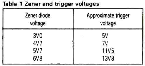
Table 1 provides an estimate of the power supply's changeover point voltage in addition to a range of commonly utilized zener voltages.

This NAND gate based low battery alarm circuit may trigger an alarm whenever the power supply voltage falls to around 11.5V, in which case it must employ a 5V6 zener diode.
If you want the alarm to go off when the voltage drops to around 7V, try a 4V7 zener diode.
These voltages depend on specific components, therefore you may need to research them (the gate changeover voltage and the zener diode voltage can both be somewhat variable).
The NAND gates IC1d and IC1c comprise the low voltage trigger.
The main part of the NAND gate astable multivibrator is the gates IC1c & b, in tandem with any associated components. The piezo buzzer is driven in the reverse orientation by the astable multivibrator.
Because of this, whenever the voltage of the power supply exceeds the voltage which increases the voltage level of the zener diode over the flipping point of the first gate, the buzzer is muted.
On the other hand, when the power supply voltage drops and the first gate's input voltage falls below its toggle point, the buzzer sounds.
Testing Procedure
To make sure your low battery alarm is running well, it's necessary to have a power supply with an output voltage which adjusts continuously and a voltmeter which can display the voltage range of the power supply.
Connect the voltmeter to the power source so you can see the output voltage.
Adjust the power supply output voltage to a higher value should you wish the system to emit its warning.
Should you want the device to emit sound as the voltage dips further down, say, 7V, configure the power supply to around 10V.
Now connect the gadget to the power supply.
As long as you select the correct zener diode, virtually nothing should happen at all.
Watch the voltmeter's readout as you progressively lower the power source's output voltage.
When the voltage drops, the piezo buzzer should sound, indicating that the device is operational.
Under this point, the buzzer begins to sound, and once you exceed it, it shuts off.
If the zener diode choice turns out well, the voltage limit where the piezo buzzer activates will match the voltage you have selected.
Leave a Reply