The article explains 24 types of amplifier configurations using op amps.
Difference Amplifier Circuit
By simply employing a couple of inputs as demonstrated, a difference amplifier containing the differential between U1 and U2, times a gain factor results.

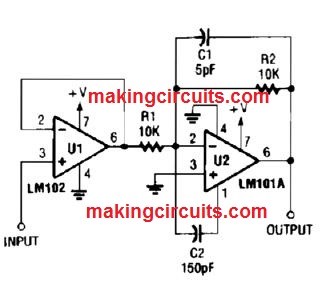
Fast Inverting Amplifier With High Input Impedance Circuit
U1 is utilized like a voltage follower to supply inverter U2, Since U1 is with the voltage follower circuit, it shows a higher input impedance.
Noninverting AC Amplifier Circuit
A universal noninverting ac amplifier for sound of other low frequency implementations is displayed here, Layout equations are shown in this figure.

Nearly every standard objective op amp can easily be employed for U1.
Inverting Summing Amplifier Circuit
The output of U1 is obtained by adding V1, V2, and V3, and multiplying by R1/R4, R2/R4, respectively. R1, R2, R3 are chosen as needed for desired benefits, R4 influences gain of all these inputs.

Nonlinear Operational Amplifier With Temperature Compensated-Breakpoint
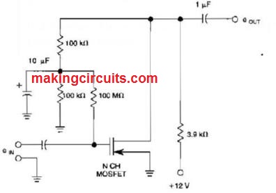
Mosfet High Impedance Biasing Method Circuit
High impedance biasing method for an N channel MOSFET to create a linear inverting amplifier.
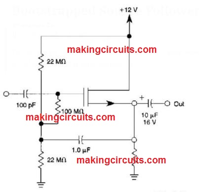
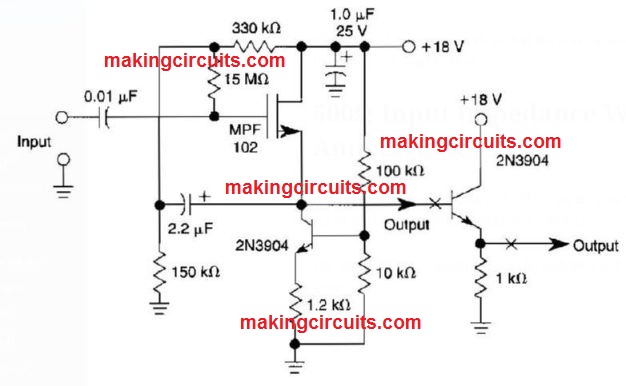
Bootstrapped Source Follower Circuit
This bootstrapped source follower employs an N channel MOSFET. It includes with a higher input impedance.
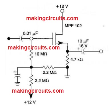
30 MΩ JFET Source Follower
This JFET source follower employs an MPF102 using offset biasing. It includes an input impedance of >30 MΩ
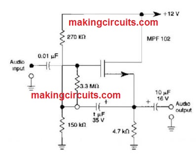
JFET Source Follower Circuit
The circuit employs positive gate bias to enhance the functioning point for improved dynamic range.
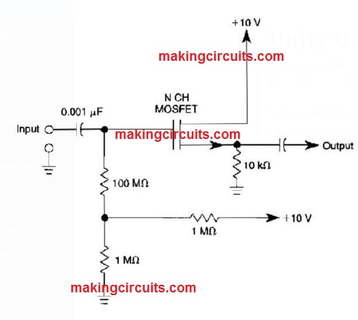
Unity Gain Noninverting Amplifier Circuit
Biasing techniques for an N channel MOSFET to make a unity gain noninverting amplifier or source follower.
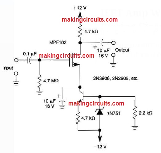
JFET Amp With Current Source Biasing Circuit
A current source (MPF102) in the source pin of bipolar transistor 2N3906 enables exact charge of drain current.
Electret Mike Preamp Circuit
This circuit works with an electret microphone and can be used for several applications.
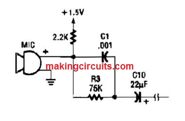
A 1.5-V battery is employed. C1 and R3 supply treble boost/bass cut; they could be eradicated, if preferred.
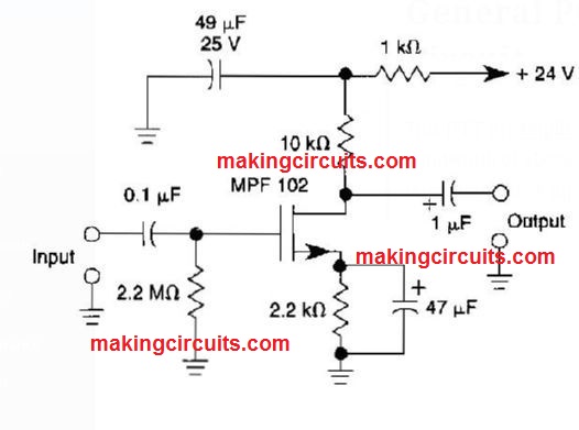
General Purpose JFET Preamp Circuit
This JFET preamplifier includes a gain of around 20 dB and also a bandwidth of above 100 kHz. Its helpful like a low level sound amplifier for large impedance inputs.
FET Amplifier With Offset Gate Bias Circuit
With this amplifier circuit, the gate of the MPF102 is biased using an external voltage.
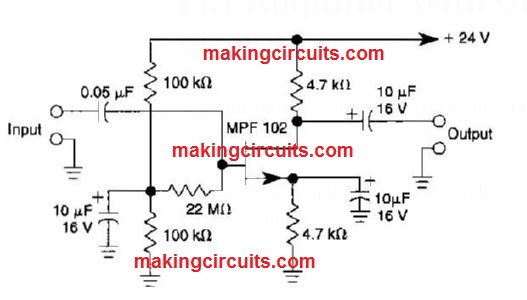
This circuit accomplishes stronger regulation of the working point and biasing conditions.
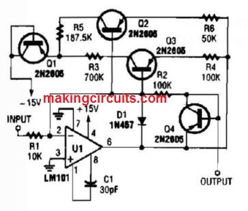
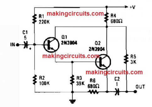
Push Pull Darlington Amplifier Circuit
This circuit incorporates a larger Z input and push pull output through the output obtained around R4 and R6.
Noninverted Unity Gain Amplifier Circuit
An op amp works extremely well as a unity gain amplifier simply by linking its Output to its inverting input as demonstrated.
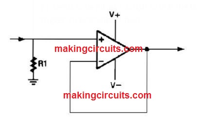
R1 needs to be lower enough so that the bias current of the op amp won't trigger an noticeable offset.
500Ω Input Impedance With JFET Amp Circuit
A current source employing a 2N3904 transistor as well as bootstrapping, accomplishes an input impedance of 500 MQ.
The other ZN3904 transistor could be included at X to lessen the output impedance.
Discrete Current Booster Amplifier Circuit
Appropriate as a line driver, this circuit is able to be used in several related sound applications.
Frequency Counter Preamp Circuit
Using the LM733 or NE592, the preamp demonstrated includes a bandwidth of 100 MHZ.
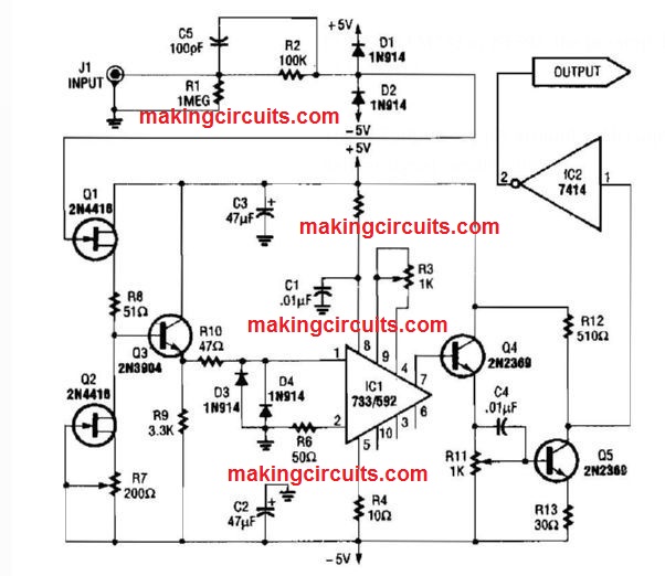
The FET inputs supply around 1~MQ input impedance. Q4, Q5, and IC2 deliver signal conditioning.
Audio To UHF Preamp Circuit
The Signetics NE5204 or NE5205 can be employed within this AF to 350-MHZ (-3O dB) preamp.
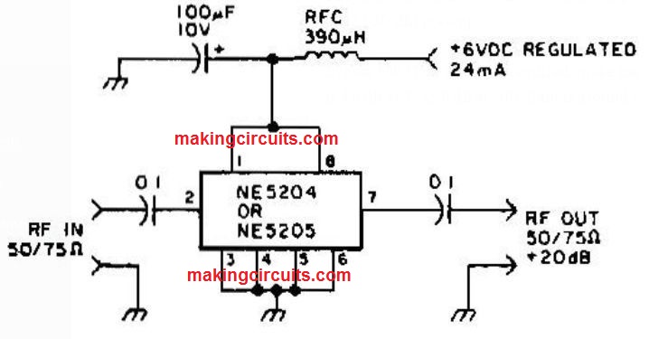
In case 600 MHZ @ 3 dB is required, make use of NE5205. The sound figure is 4.8 dB at 75 Ω, 6 dB at 50Ω. Gain is around +20 dB above the passband.
Voltage And Current Protected Intrinsically Safe Opamp Circuit
The circuit is built to operate an external load. An error situation in the external load circuit can provide extreme current or voltage feedback into the line drive circuit.
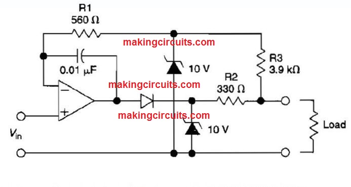
In case too much voltage seems from the load, the a couple of zener diodes may fix that voltage to a safe level, that in this instance is 10 V.
The current in the zener diodes, op amp, and the remainder of the circuitry is fixed to some secure level by resistors R1, R2, and R3. D1 guards the op amp output stage through 10 V showing up around the clamp diodes below a fault situation.
The benefit of this circuit is that, even though it's developed as unity gain buffer, a similar methods could be placed on inverting, noninverting, or differential gain stages.
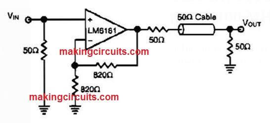
Current Feedback Amp Delivers 100 ma @ 100 MHz Circuit
Making use of a NS LM6181, this IC is handy in cable drivers. The supply voltage is +/-5 V to +/-15 V.
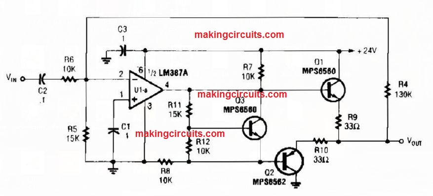
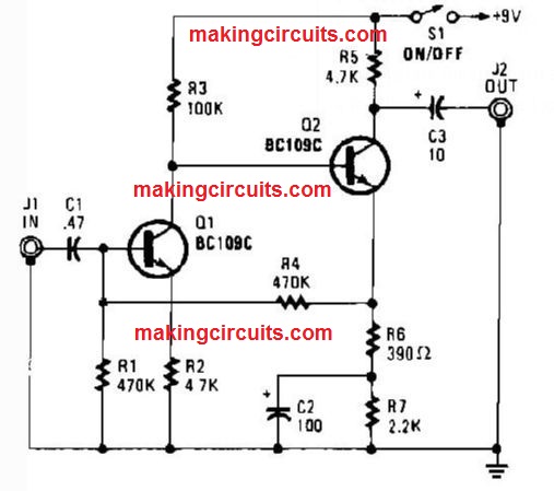
General Purpose Preamplifier Circuit
Appropriate for standard audio applications, the preamp circuit works with a feedback pair, Current gain is fixed with the ratio of (R4 + R6)/R4.
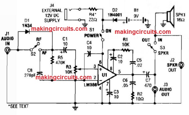
Test Bench Amplifier Circuit
This amplifier could be beneficial in repairing or bench testing as a signal tracer or as a universal module in several applications.
Unfortunately drawings of circuits are blurred.
What does it mean, that “R1 needs to be lower enough so that the bias current of the op amp won’t trigger an noticeable offset”. What is order of magnitude of value R1?
You can think of bias current as leakage from the op-amp. It is usually in the microamp to picoamp range. Check the data sheet for the ranges. Then using Ohm’s law, you can calculate how much voltage the current will generate. If the voltage offset is to much, reduce the resistor value. Best choice would be to match the output resistance of whatever is feeding the voltage follower circuit.