This circuit will keep the car interior lights switched ON for some time after the ignition is turned OFF so that the driver is able to exit the car comfortably without missing anything important inside the car.
ALMOST ALL MODERN CARS are usually installed along with door switch powered courtesy lights.
Beneficial devices, although not pretty as helpful since they could be due to the fact that they thus organized the light is extinguished the instant you shut the door and simply when you require light to search the ignition switch, do up your seat belt etc.
Simply how much better in case the internal light remained on for a couple seconds as soon as the door is shut. This little project does exactly that.
It possesses a four -second delay (approx)after which the interior light gradually dims - being lastly extinguished soon after 10 or 12 seconds.
The unit is quite simple to set up and as soon as tested and correctly protected it might be wired across among the car door switches.
In operation, after having a short delay the lights will certainly slowly dim right up until they may be absolutely extinguished.
There is absolutely no battery drain in the off state as the unit simply functions through the delay period once the door is shut down.
How the Car Interior Lights Delay Off Circuit Works
In a car from where the negative terminal of the battery is attached to the chassis the negative wire of the unit (emitter of Q2) is linked to chassis and also the positive wire (case of 2N3055) is attached to the wire going to the switch.
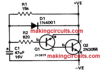
In a car possessing a positive earth system this connection sequence is changed. Once the switch shuts (door open) C1 is discharged through D1 to zero volts and once the switch opens C1 charges up through R1 and R2.
Transistors Q1 and Q2 are linked as an emitter follower (Q2 just buffers Q1) hence the voltage across Q2 raises gradually as C1 charges. Thus Q2 works similar to a low resistance in parallel with the switch keeping the lights on.
The value of C1 is chosen in a way that an effective light level is acquired for around four seconds, thereafter the light diminishes till in around 10 seconds it is out totally with various transistor gains along with variation in current drain as a result of specific kind of car the timing may vary, however this might be merely adjusted by choosing C1.
I am making a simple cloths pin trip wire circuit. It works by making a contact of an animal pulling my trip wire and removing a plastic insulator between two screws attached to a cloths pin. At this point I am allowing the positive side of a car battery to complete a circuit to the 12 VDC strobe light ( I do not want an audio circuit ) , the negative side of the battery is attached to frame ground.
At this time I am wanting to activate a 12 VDC strobe light for only up to 15 seconds then I want the light to go out.
I will at a later time go and reset the plastic strip between the screws on the cloths pin.
Can you help me design the circuit
You must allow the 12V to trigger a 15 second transistor monostable, the output of the monostable could be used for operating the strobe.