The submit offers a basic cellphone activated remote control circuit which can be utilized as a cellphone controlled remote car starter. The unit would certainly cost less than $20 to build.
I have already taken care of more than a few fascinating cellphone remote control circuits within this blog, most of which could be executed to manage or toggle some electrical equipment remotely utilizing ones own cell phone, exclusively.
The fundamental cellphone regulated relay circuit stage associated with all the earlier circuits may be additionally efficiently employed for beginning the ignition system of a vehicle, by means of the owners cell phone. The schematic for the same might be observed below and may understood with the following justification:
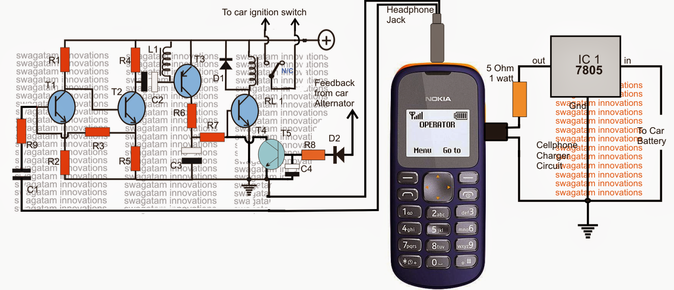
The design is essentially a transistorized audio amplifier circuit, which can be placed for amplifying the designated ringtone from the nearby cell phone modem. The cellphone demonstrated with the circuit remains completely associated with the circuit and forms the essential section of the whole program.
The diagram demonstrates a NOKIA 1280 cellphone as the modem, in spite of this any inexpensive cellphone could be raised for the reason supplied the cellphone consists of the "assign tone" benefit discretely for the specific preferred numbers.
The number of the owner or the user is first stored and assigned with an appropriate ringtone accessible within the cellphone modem to ensure that the modem replies simply to the owners phone and not to some other irrelevant numbers. The default ringtone of the modem is placed to "empty" to be able to mute all other unwanted calls.
When the owner calls the moden cellphone, the ringtone is identified by the circuit and amplified to a level adequate for the relay to get energized. The relay continues energized for as long as the call stays linked.
Considering that the relay contacts are set up or built-in with the ignition switch of the car, instantly causes the ignition method of the vehicle beginning the engine and the whole system.
A feed back from the initiated alternator ensures that the relay is immediately shut off regardless of the call duration from the owner's cellphone.
The car ignition hence has the capacity to begin without the owner or the driver needing to get inside the car and undergo the manual procedures. The car begins remotely by way of the owner's cell phone, a fail proof and a foolproof process yet as cheap as you are able to consider.
Parts List for the cell phone managed car ignition starter circuit
R1 = 22k
R2 = 220 Ohms,
R3 = 100K,
R4,R6,R7 = 4K7
R5 = 1K
R8 = 33K
R13 = 100 ohms,
T1, T2, T4, T5 = BC547
T3 = BC557,
C1 = 0.22uF
C2,C3, C4 = 100uF/25v
D1, D2 = 1N4007
L1 = 40 mH coil, example: a piezo buzzer coil will do.
diode = 1N4007
Relay = 12V/SPDT
Modem = NOKIA 1280
The charger section is demonstrated in the diagram, and ought to stay associated comtely with the connected cellphone modem.
hi sir, plse u are very good man that u can able to review various types of circuits may god bless u.
you are most welcome!!