• Skip to main content
  • Skip to primary sidebar

Making Easy Circuits

Learn and build electronic circuits

You are here: Home / Battery Chargers / Cellphone Power Bank Circuit you can Make at Home

Cellphone Power Bank Circuit you can Make at Home

Last Updated on January 10, 2018 by Admin Leave a Comment

This simple cellphone power bank circuit charger can be built at home and used for emergency charging your cell phone anytime anyplace regardless of an AC mains outlet or input availability.

The idea is all about using a 4 AAA N-Cd cells in series and then keeping it fully charged through a suitable SMPS charger circuit. Once charged this unit may be carried with you whenever you are outdoors and can be simply plugged in with your cell phone for getting it quickly charged.

What you will need to make this super simple Power Bank Circuit:

A 4 AAA cell holder box as show below:

Battery Holder 3xAA 1

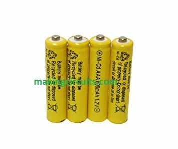
Four numbers of AAA Ni-Cd Cells, as show below:

713Ld3td9L. SX355

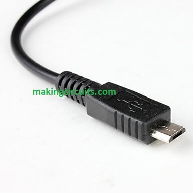
And a charger connector with wire as per your mobile's pin specification, generally it will be as shown below:

charging prob

Procedure:

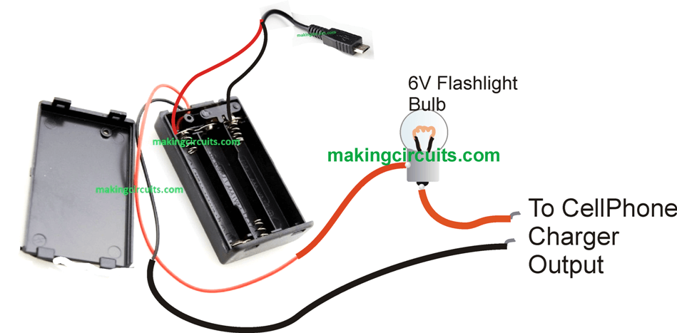
The procedure for making this power bank circuit is really simple. After procuring the above material, connect the above connector pin wire ends to the points where the red/black wires are connector in the battery holder box.

Make sure the polarity is correct, although that won't burn yourself cellphone, rather it just won't initiate the charging when you connect the power bank to your mobile phone, so pay special attention on the connector polarity while soldering it with the battery holder box.

We have not cut or removed the existing red black wires of the holder because we want to use it for charging the power bank when it's at home and needs a recharge and for being at ready stand by position.

For charging the 4 AAA N-iCd cells, you can use any standard 5V adapter and connect it with the holder red/black wire through a 6V flashlight bulb as shown below:

The 6V bulb makes sure that the cells are never over charged and it restricts the current to safe limited range

Cellphone Power Bank Circuit you can Make at Home


How to Charge the Power Bank Battery:

After you have finished making the above power bank circuit, simply fix the 4 AAA Ni-Cd cells inside the holder, and next feed a 5V DC 1 Amp to the indicated wire ends, from any suitable source such as from an USB port, a 5V SMPS adapter etc.

When connected, the 6V lamp will light up brightly indicating that the battery pack is charging, gradually in the course of time this 6V bulb will start getting dimmer in response to the charging of the cells, and finally shut down when the battery pack is fully charged. You can now remove the battery box from the 5V source.

Now this battery power bank is ready for charging you cellphone whenever you go out for traveling or camping etc.

You can test the power bank back up output by plugging the charging pin with your cell phones charging input.

If you have any related questions regarding power bank circuit please feel free to express them below in the comment box.

You'll also like:

  • 1.  How to Build a Boost Charger Circuit for Super Capacitors
  • 2.  How to Charge a Battery using an SMPS
  • 3.  How to Make a Lithium Polymer Battery Charger Circuit
  • 4.  How to Correctly Calculate Solar Panel, Inverter, Battery Charger
  • 5.  Microcontroller MPPT Circuit for Final Year Project
  • 6.  Battery Charger for Positive Earth Cars

About Admin

Hey friends, Thanks a bunch for stopping by this site! I am an engineer with a Bachelor of Engineering in Electronics and Telecommunication. One of my passions is gathering information from all sorts of electronics books and tutorials. I then take that information and compile it into a language that is super easy to understand. My goal is to make those complex electronics circuit concepts and technical terms much more accessible for all the new and budding electronics engineers out there. I can also design customized circuit diagrams as required by the users.
If you have any questions related to this field, please do not hesitate to drop a comment! I am always here and ready to help you out with any queries you might have. I cannot wait to hear from you!

Reader Interactions

Leave a Reply Cancel reply

Your email address will not be published. Required fields are marked *

Primary Sidebar

Categories

  • 3 Phase (4)
  • 8051 Microcontroller (1)
  • Arduino (11)
  • Audio and Amplifier (102)
  • Automation (8)
  • Battery Chargers (64)
  • Bicycle Projects (4)
  • Car and Motorcycle Projects (39)
  • Datasheets (10)
  • DIY Projects (5)
  • Electrical (15)
  • Free Energy (6)
  • Games Projects (2)
  • High Voltage (14)
  • Hobby Projects (30)
  • Household Circuits (2)
  • IC 555 Circuits (5)
  • Ignition Circuits (2)
  • Indicators (50)
  • Infrared (6)
  • Inverter Circuits (29)
  • Lights and Lamps (97)
  • Medical (8)
  • Meter and Tester Circuits (38)
  • Motor Driver (17)
  • New Circuits (56)
  • Oscillators (30)
  • Pets and Pests (5)
  • Power supply (80)
  • Protection Circuits (25)
  • PWM (9)
  • Remote Control (20)
  • Security and Alarm Circuit (48)
  • Sensors and Detectors (66)
  • Signal Processor (23)
  • Solar Controller Circuits (62)
  • SSR (3)
  • Temperature Controller (20)
  • Timer (25)
  • Transformerless (7)
  • Transmitters (12)
  • Tutorials (45)
  • UPS (2)
  • Voltage Regulators (57)
  • Water Sensor and Controller (29)
  • Home
  • Privacy Policy
  • Contact
  • Disclaimer
  • Copyright

© 2025 · Making Easy Circuits