• Skip to main content
  • Skip to primary sidebar

Making Easy Circuits

Learn and build electronic circuits

You are here: Home / Power supply / Very Cheap and Simple SMPS Circuit Using MJE13005

Very Cheap and Simple SMPS Circuit Using MJE13005

Last Updated on December 14, 2024 by Admin Leave a Comment

The circuit we are talking about in this article is probably one of the simplest and most cost-effective options out there. This is mainly because it uses a very small number of components and putting the whole circuit together is really straightforward.

How the Circuit Works

When we look at how this circuit functions, we find that it typically follows a certain structure known as SMPS topology, which includes some standard phases and specifications. We can break these down like this:

First up, we have what we call the input stage. This stage includes a main rectifier stage that is pretty clear and straightforward. After that, there are several important protection components that come into play.

These protective elements can be things like an MOV or an NTC or sometimes even a combination of both. Their main job is to help reduce high voltage transients which can be harmful.

Next, we move on to the following phase where we find a mosfet-based integrated circuit paired with the primary side of a compact transformer. This setup is what creates the necessary oscillations that the circuit needs to function properly.

The integrated circuit is usually a modern chip that comes packed with lots of features and capabilities which makes it quite advanced.

On top of that, the secondary side of the transformer connects to the mosfet IC through an optocoupler. This optocoupler plays a crucial role in regulating the output voltage so that it stays at a fixed level as specified.

However, when we look at the suggested design for this inexpensive SMPS circuit, we notice that it does not really have many of these complications and instead relies on a very simple setup.

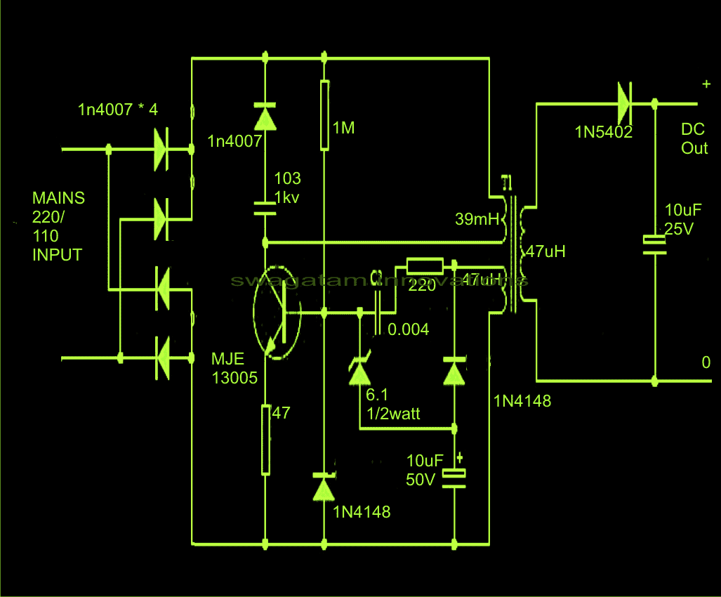
Interestingly enough, there is no protection on the input side because it has been replaced with something called a snubber network that surrounds the transistor. Plus, the sturdy MJE13055 transistor is likely strong enough to handle most situations without any issues.

As for the two windings on the primary side, they are arranged in such a way that when you turn the switch ON, the circuit starts oscillating almost immediately at around 100 kHz.

The output voltage is generally determined by what happens on the secondary winding, and just to keep things simple, there are no optocouplers or zener diodes included in this design.

That said, while this circuit is quite basic and easy to understand, it could potentially be vulnerable at some point over time due to its simplicity.

cheapestsmpscircuit

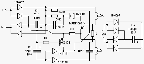
The below show design is yet another identical  simple 220V SMPS circuit design you can try to build at home:

swps 2

You'll also like:

  • 1.  Simple Short-Circuit Protection for Power Supplies
  • 2.  Designing a IC 723 Power Supply with Variable Voltage and Current
  • 3.  4.5 V, 6 V, 9 V , 12 V Power Supply Circuit
  • 4.  Simple 12V 500mA SMPS Circuit
  • 5.  High Current Voltage Regulator Circuit
  • 6.  220V to 12V SMPS Transformerless Power Supply Circuit

About Admin

Hey friends, Thanks a bunch for stopping by this site! I am an engineer with a Bachelor of Engineering in Electronics and Telecommunication. One of my passions is gathering information from all sorts of electronics books and tutorials. I then take that information and compile it into a language that is super easy to understand. My goal is to make those complex electronics circuit concepts and technical terms much more accessible for all the new and budding electronics engineers out there. I can also design customized circuit diagrams as required by the users.
If you have any questions related to this field, please do not hesitate to drop a comment! I am always here and ready to help you out with any queries you might have. I cannot wait to hear from you!

Reader Interactions

Leave a Reply Cancel reply

Your email address will not be published. Required fields are marked *

Primary Sidebar

Categories

  • 3 Phase (4)
  • 8051 Microcontroller (1)
  • Arduino (11)
  • Audio and Amplifier (102)
  • Automation (8)
  • Battery Chargers (64)
  • Bicycle Projects (4)
  • Car and Motorcycle Projects (39)
  • Datasheets (10)
  • DIY Projects (5)
  • Electrical (15)
  • Free Energy (6)
  • Games Projects (2)
  • High Voltage (14)
  • Hobby Projects (30)
  • Household Circuits (2)
  • IC 555 Circuits (5)
  • Ignition Circuits (2)
  • Indicators (50)
  • Infrared (6)
  • Inverter Circuits (29)
  • Lights and Lamps (97)
  • Medical (8)
  • Meter and Tester Circuits (38)
  • Motor Driver (17)
  • New Circuits (56)
  • Oscillators (30)
  • Pets and Pests (5)
  • Power supply (80)
  • Protection Circuits (25)
  • PWM (9)
  • Remote Control (20)
  • Security and Alarm Circuit (48)
  • Sensors and Detectors (66)
  • Signal Processor (23)
  • Solar Controller Circuits (62)
  • SSR (3)
  • Temperature Controller (20)
  • Timer (25)
  • Transformerless (7)
  • Transmitters (12)
  • Tutorials (45)
  • UPS (2)
  • Voltage Regulators (57)
  • Water Sensor and Controller (29)
  • Home
  • Privacy Policy
  • Contact
  • Disclaimer
  • Copyright

© 2025 · Making Easy Circuits