Here we talk about the cheapest and simplest solar battery charger circuit. It has only two parts – a solar panel and a diode. That is it! But still, it works. No let us understand how.
Understanding the Circuit Working
So we take a 16V 1A solar panel which gives free power from the sun. This power is used to charge a 12V 7Ah battery. But wait, we cannot just connect the solar panel directly because at night, the battery might discharge back into the panel.
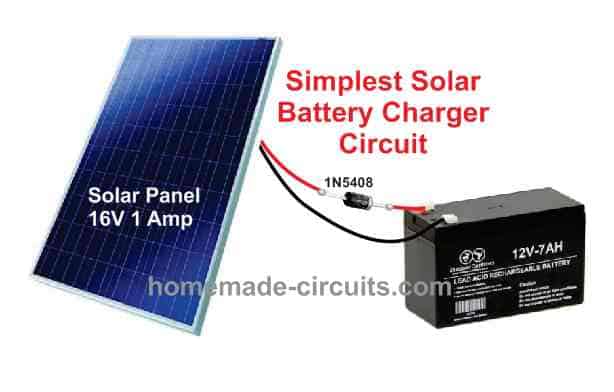
That may be bad, right? So to stop this reverse current, we add a 1N5408 diode in series with the positive wire.
Now this diode is important. It allows current to flow only from the panel to the battery but not backward. So at night, the battery stays safe.
But we have one problem – the diode drops some voltage about 0.7V. So if the solar panel gives 16V, after the diode we get 15.3V. That looks fine because a 12V battery needs around 14V to 15V for charging.
Ok, now the charging process. When the sun is strong, then panel gives full 1A current, so the battery charges faster. When the sun is weak then the charging slows down.
But one issue is there, we have no overcharge protection! So we must disconnect the battery manually when fully charged. If we leave it for too long, the battery may overcharge and lose life.
Now let us talk about connections. Very easy – solar panel positive → diode anode (unmarked side), then diode cathode → battery positive. The solar panel negative → battery negative. That’s all, done!
So now we have a super simple solar charger, no ICs, no resistors, nothing extra. Just a panel and a diode. Perfect for small applications where we can manually monitor the battery. Cheap and effective….
Ok now let us see how we build this simple solar charger properly. Even though it is just a panel and a diode, if we do not do things right, problems will happen. So let us go step by step.
- Choosing the Right Diode (Very Important!)
Now we use a 1N5408 diode because it handles 3A current and has low voltage drop (0.7V). But if we use a small diode like 1N4007 (1A) then it may burn if the panel gives more current. So always use a diode that can handle more current than the panel’s maximum output.
- Proper Soldering and Connections
Next, we must solder the diode firmly. If the solder joint is weak or loose then it will heat up and stop working. Also if we connect the diode backward then battery won’t charge at all! So, remember this:
Anode (unmarked side) → Solar panel positive
Cathode (marked side) → Battery positive
- Wire Thickness and Length (Very Crucial!)
Now, we must use thick wires from the panel to the battery. If wires are thin then they drop voltage, and charging slows down. Also keep wire short as much as possible because long wires create resistance which again reduces charging speed.
- Mounting the Solar Panel (Must Face the Sun!)
Now the solar panel must be placed directly under sunlight, not in shade, not behind glass, not at a bad angle. If sunlight is weak then battery will charge very slowly or not at all. So tilt the panel towards the sun properly especially in the afternoon when sunlight is strong.
- Manually Stopping Overcharge (Warning!)
Ok now this circuit has no overcharge protection. If we forget to disconnect the battery, then it may overcharge which reduces battery life or may even damage it. So always check the battery voltage with a multimeter. When it reaches around 14.4V, we must disconnect it.
- Waterproofing (Important for Outdoor Use!)
If we place the charger outdoors, rain or dust can damage connections. So we must cover the diode and wires properly with heat shrink tube or tape. The solar panel itself is waterproof but the connections are not!
- Testing Before Connecting the Battery
Now before we connect the battery, we must check the output voltage. First we measure the solar panel voltage without load (it should be around 16V in full sun). Then we measure after the diode (should be around 15.3V). If these readings are fine then we connect the battery.
Final Warning: Do Not Reverse Battery Terminals!
If we accidentally swap battery terminals, then diode may burn, or even worse, the battery may spark and get damaged. So please double-check positive and negative before connecting!
So now if we follow these steps, this simple charger will work perfectly. But remember, you must keep checking the battery manually to prevent overcharging. Simple, cheap but we must use it carefully!
Leave a Reply