Thefts in automobiles of precious accessories like spot lamps and fog lamps are on the rise. Backed up with a spanner, and provided a few moments uninterrupted, the earnest thief can often make a robbery worth over many 100 $.
How the Circuit Works
The low-cost protection alarm circuit explained in this article could safeguard these important merchandise, and may additionally be applied to prevent the fraud of accessories from interior of the car, for instance radios and FM players.

The entire circuit of the alarm is demonstrated in the figure above. Gates N1 to N4 create a 5-input OR gate, however the range of inputs can simply be increased with the addition of more gates. Once the vehicle is in the parked position (with the ignition turned off) R1 retains the inputs of N5 low, to ensure the output is high.
The inputs of N1 to N4 are kept low through the lamp filaments, etc. which need to be protected. The N4 output is as a result low, causing the N6 output to be high, T1 is thus switched on, enabling T2 to be switched off and relay Relay 1 is deactivated.
In case of an accessory becoming detached by a crook (let's say, the light fixture attached to input E1), then this relevant input for the OR gate will be drawn high by means of the 10 k input resistor.
The N4 output subsequently turns high, causing N6 output to go low, forcing T1 to be switched off and switch ON T2, and causing relay 1 to power ON, which eventually switches ON the the car horn alarm.
During the periods when the ignition switch is closed the N5 output stays low, causing the N6 output to be forever high, as a result this disables the alarm.
This stops the alarm from turning ON in case one of the gadgets is started up.
Needless to say, the alarm may still sound if an accessory is turned ON with the the ignition being in the switched off condition. This inhibits spot lamps and fog lamps from inadvertently getting left on while the vehicle is without an occupant.
On the other hand, all these accessories could be hard-wired through the ignition switch to ensure that this is not able to happen. A surplus benefit could be that the security alarm will likely turn ON in case of a lamp filament getting fused.
However, given that a replacement lamp might not often be accessible, a hidden 'termination' switch (S1) is necessary…
Accessories inside the car, such as radios and cassette players, may also be protected by connecting a wire from one of the alarm inputs to the earthed case of the equipment.
When the thief cuts this wire to remove the equipment then the alarm will sound. Of course, this facility should only be regarded as a backup to an alarm that prevents a thief entering the car in the first place!
Where lamps are wired in pairs the alarm will, of course, not sound until both have been disconnected.
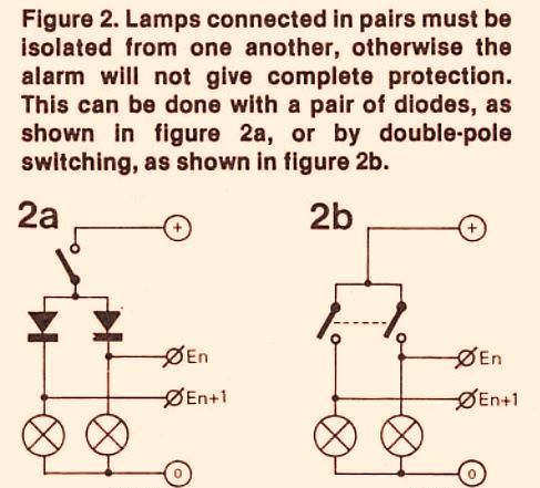
To overcome this disadvantage a diode of suitable current rating can be wired in series with each lamp, as shown in figure above. Since there is a 0.7 V voltage drop across a diode, a better idea would be to use a double-pole switch for the set of lamps being protected, as shown in figure 2b.
Leave a Reply