• Skip to main content
  • Skip to primary sidebar

Making Easy Circuits

Learn and build electronic circuits

You are here: Home / Power supply / Constant Current Adapter Circuit

Constant Current Adapter Circuit

Last Updated on May 8, 2020 by Admin Leave a Comment

It is very necessary that this electronics enthusiast needs a constant current source.

If this type of need does occur, for instance for test requirements, it can be a item of equipment which is not normally accessible.

On the other hand, it is far from essential to create a entire constant current source for every application.

It is sufficient to have a adapter which can be linked to an available power supply whenever a constant current source is essential.

The recommended constant current adapter circuit has yet another beneficial application: the asymmctric-to-symmetric power supply converter at the front end of the frequent current adapter can be utilized independently to power an amplifier or related circuit.

block diagram
constant current adapter

Most amateur constructors use a mains power supply using a variable output voltage as high as 30 V and a current output of around 200 mA (or higher).

This particular supply then can be employed to power the constant current adapter.

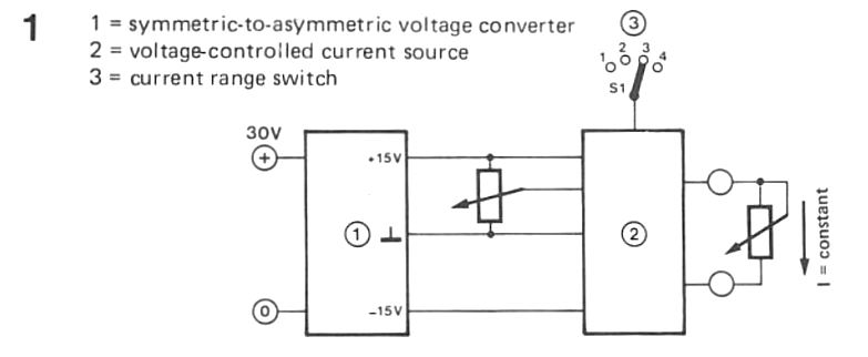
The asymmetric-to-symmetric converter including IC1 and transistors T1 and T2 offers an efficient output voltage of ± 15 V over the two capacitors C2 and C3.

This particular shaped supply can be employed individually provided the necessary output current is no higher than about 50 mA.

How the Circuit Works

We will right now analyze the constant current adapter itself in better aspect.

The asymmetric-to-symmelric voltage converter is needed to power the functional amplifier IC2.

This opamp can be used as the current source and is also regulated by the potential divider composed of potentiometer P1 and resistors R3 and R4.

Potentiometer P1 are adjustable to offer an output voltage of between 1. 5… 15 V. A constant current will certainly flow by means of load resistor R1, which can be determined by the voltage setting of P1 and on the range picked by switch S1.

The Constant current adapter circuit is certainly that, inspite of the specific range, the current via R1 is dependent upon the setting of P1.

Transistors T3 and T4 just form a buffer level.

The output current of the adapter could be worked out through the formula.

I = 0.1 x UP1 / R10 or R11 or R12 or R13


Potentiometer P1 ought to discover a range from 1 to 10 in order that it is a lot easier to manage the specified current.

Based on the setting of the range switch S1, the current can then be deduced using the multiplication element presented in the table below.

Potentiometer P2 needs to be altered in the beginning in order that an output current of 10 A is acquired when SI is in position '1' and P1 is placed at minimum output

You'll also like:

  • 1.  +/-5V to 12V Adjustable Power Supply Circuit
  • 2.  1.2 V to 32 V 10 Amp Adjustable Voltage Power Supply using LT1038
  • 3.  Build this One Transistor Regulated Power Supply Circuit
  • 4.  Simple 12V 500mA SMPS Circuit
  • 5.  Constant Current Circuit for High Watt LEDs
  • 6.  220V Power Supply Circuit using MJE13005 without Transformer

About Admin

Hey friends, Thanks a bunch for stopping by this site! I am an engineer with a Bachelor of Engineering in Electronics and Telecommunication. One of my passions is gathering information from all sorts of electronics books and tutorials. I then take that information and compile it into a language that is super easy to understand. My goal is to make those complex electronics circuit concepts and technical terms much more accessible for all the new and budding electronics engineers out there. I can also design customized circuit diagrams as required by the users.
If you have any questions related to this field, please do not hesitate to drop a comment! I am always here and ready to help you out with any queries you might have. I cannot wait to hear from you!

Reader Interactions

Leave a Reply Cancel reply

Your email address will not be published. Required fields are marked *

Primary Sidebar

Categories

  • 3 Phase (4)
  • 8051 Microcontroller (1)
  • Arduino (11)
  • Audio and Amplifier (102)
  • Automation (8)
  • Battery Chargers (64)
  • Bicycle Projects (4)
  • Car and Motorcycle Projects (39)
  • Datasheets (10)
  • DIY Projects (5)
  • Electrical (15)
  • Free Energy (6)
  • Games Projects (2)
  • High Voltage (14)
  • Hobby Projects (30)
  • Household Circuits (2)
  • IC 555 Circuits (4)
  • Ignition Circuits (2)
  • Indicators (50)
  • Infrared (6)
  • Inverter Circuits (29)
  • Lights and Lamps (97)
  • Medical (8)
  • Meter and Tester Circuits (38)
  • Motor Driver (17)
  • New Circuits (56)
  • Oscillators (30)
  • Pets and Pests (5)
  • Power supply (81)
  • Protection Circuits (25)
  • PWM (8)
  • Remote Control (20)
  • Security and Alarm Circuit (48)
  • Sensors and Detectors (66)
  • Signal Processor (23)
  • Solar Controller Circuits (61)
  • SSR (3)
  • Temperature Controller (20)
  • Timer (25)
  • Transformerless (7)
  • Transmitters (12)
  • Tutorials (45)
  • UPS (2)
  • Voltage Regulators (57)
  • Water Sensor and Controller (29)
  • Home
  • Privacy Policy
  • Contact
  • Disclaimer
  • Copyright

© 2025 · Making Easy Circuits