• Skip to main content
  • Skip to primary sidebar

Making Easy Circuits

Learn and build electronic circuits

You are here: Home / Audio and Amplifier / Constant Volume FET Amplifier Circuit

Constant Volume FET Amplifier Circuit

Last Updated on June 6, 2025 by Admin 6 Comments

In numerous occasions it is desirable to obtain an amplifier that gives an output signal of constant amplitude for numerous input signal levels and with the very least distortion.

A traditional way out of this challenge is to use a nonlinear amplifier.

An operational, as an illustration, run as a nonlinear amplifier if 2 antiparallel diodes are included in the feedback loop.

This program, nevertheless, while offering an output signal of close to constant amplitude, carries a setback: severe distortion.

How it Works

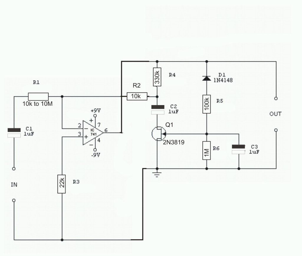
A more exquisite solution is to apply a constant volume FET amplifier circuit as shown in Fig below.

In such cases, the nonlinear ingredient is restored with the FET (Q1) and its associated elements.

When a small operational signal (741) is applied, its output is smaller.

As a result, the gate of the FET receives an incredibly minimal negative bias and the resistance between drain and source is substantial. As a result, the voltage gain is high.

The opposite happens in the event the input signal is bigger. Consequently, the common measure of the output signal self-regulates between 1.5V and 2.85V over a range of 50: 1 difference in the degree of the input signal without producing audible distortion.

The value of R1 is determined by the optimum expected amplitude of input signal and is established on a per 200k volt RMS. As an illustration, to satisfy up to 50Vrms signals R1 must 10M.

Circuit of a constant volume FET amplifier

You'll also like:

  • 1.  Audio Limiter Circuit
  • 2.  How to make a Extended Telephone Ring Amplifier/Repeater Circuit
  • 3.  Simple 250 Watt Amplifier Circuit
  • 4.  Scratch And Rumble Filter Circuit
  • 5.  Simple Home Theater Circuit Explained
  • 6.  Door Buzzer Circuit

Tagged With: Audio

About Admin

Hey friends, Thanks a bunch for stopping by this site! I am an engineer with a Bachelor of Engineering in Electronics and Telecommunication. One of my passions is gathering information from all sorts of electronics books and tutorials. I then take that information and compile it into a language that is super easy to understand. My goal is to make those complex electronics circuit concepts and technical terms much more accessible for all the new and budding electronics engineers out there. I can also design customized circuit diagrams as required by the users.
If you have any questions related to this field, please do not hesitate to drop a comment! I am always here and ready to help you out with any queries you might have. I cannot wait to hear from you!

Subscribe
Login
Notify of
6 Comments
Newest
Oldest Most Voted
Inline Feedbacks
View all comments
korpret
1 year ago

What is the function/purpose of D1? Are we rectifying and then smoothing out (by C3) the “V out” for the control of Q1’s impedance (via the Gate)?

0
Reply
Author
Admin
1 year ago
Reply to  korpret

I think your assumption makes sense; that could be the reason why D1 is included.

0
Reply
korpret
1 year ago
Reply to  Admin

Thanks!!!

0
Reply
Mike Harris
2 years ago

Frustrated by modern tv sound output I wish to build this project… my question, how do set final output volume settings?

0
Reply
Anil Kumar. K
7 years ago

Hi
1) Can I use single polarity powersupply for IC 741. If not possible, can I use other ics like LM358….?
2) Can I use 20N06 NFET insted of 2n3819….?
Thanks

0
Reply
Author
Admin
7 years ago
Reply to  Anil Kumar. K

Hi,
the diagram shows IC 741 but I won’t recommend rather it must be replaced with a low noise opamp such as LT1115 or similar,

for the fet please compare the datasheets of the two and if they match closely, they may be interchanged

0
Reply

Primary Sidebar

Categories

  • 3 Phase (4)
  • 8051 Microcontroller (1)
  • Arduino (11)
  • Audio and Amplifier (103)
  • Automation (8)
  • Battery Chargers (64)
  • Bicycle Projects (4)
  • Car and Motorcycle Projects (40)
  • Datasheets (10)
  • DIY Projects (6)
  • Electrical (15)
  • Free Energy (6)
  • Games Projects (2)
  • High Voltage (14)
  • Hobby Projects (30)
  • Household Circuits (2)
  • IC 555 Circuits (4)
  • Ignition Circuits (2)
  • Indicators (51)
  • Infrared (6)
  • Inverter Circuits (29)
  • Lights and Lamps (97)
  • Medical (8)
  • Meter and Tester Circuits (38)
  • Motor Driver (17)
  • New Circuits (56)
  • Oscillators (30)
  • Pets and Pests (5)
  • Power supply (84)
  • Protection Circuits (25)
  • PWM (8)
  • Remote Control (20)
  • Security and Alarm Circuit (48)
  • Sensors and Detectors (66)
  • Signal Processor (23)
  • Solar Controller Circuits (61)
  • SSR (3)
  • Temperature Controller (20)
  • Timer (25)
  • Transformerless (7)
  • Transmitters (12)
  • Tutorials (45)
  • UPS (2)
  • Voltage Regulators (57)
  • Water Sensor and Controller (29)
  • Home
  • Privacy Policy
  • Contact
  • Disclaimer
  • Copyright

© 2025 · Making Easy Circuits

wpDiscuz