The article explains a current controlled LED driver circuit for CREE XM-L T6 LED.
For a battery powered circuit the LED driver may very well be implemented through a current controller stage, mainly because here voltage regulation is not essential, allowing it to be avoided.
How the Circuit Works
Depending on the above inquiry, the Cree XM-L T6 LED driver ought to be operated from a 3.7V/3amp source, with a 3-way switchable dimmer regulate function.
The design could be applied utilizing the following transistorized current control stage. Despite the fact that it's not merely one of the extremely effective of the designs, the easy benefits over the slight inefficiency.
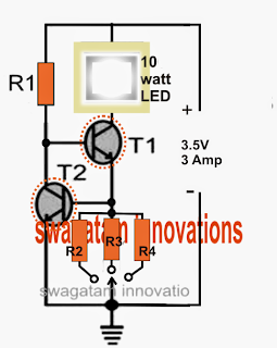
Making reference to the above diagram, the design is a simple current controlled stage where T2 signifies the maximum current limit of T1 by handling the base potential of T1.
Any time the circuit is activated, T1 is turned on through R1 illuminating the LED. The practice enables the complete current utilized by the LED to penetrate one amongst the elected resistors (R2, R3, or R4) to ground.
This produces a proportionate level of voltage across this current sensing resistor, which will kinds the activating voltage for the base of T2.
As long as this imagined voltage is higher than 0.7V, T2 is required to activate and ground the base potential of T1, therefore restricting its conduction, and consequently restricting power to the LED.
The LED is currently forced to shut, on the other hand the procedure as the LED endeavors to switched off this also commences reducing the voltage across the individual base resistor of T2.
T2 at present experience a decrease of activating voltage and switches OFF, rebuilding the LED right back its original position through T1, until again the limitation practice is activated which in turn proceeds, keeping a current governed illumination over the related LED, that may be a Cree XM-L 10 watt lamp for this reason.
In this article R4 ought to be elected to enable the LED to illuminate with optimal utilization (max brightness), that is definitely at its rated 3 amp level....R2 and R3 could be elected to deliver another required lower current operation (lower intensity) to the LED such that by locating these kind of delivers three several intensity levels for the LED.
Elements List
- T1 = TIP 41 (on heatsink)
- T2 = TIP 31 (on heatsink)
- R1 could be measured by applying the following formula:
- R1 = (Us - LEDv) x hFe / LED current
- = (3.5 - 3.3) x 25 / 3 = 1.66 ohms
- Wattage of the resistor = (3.5 - 3.3) x 3 = 0.6 watts or 1 watt
- R2, R3, R4 could be measured as:
- Low Intensity = R2 = 0.7/1 = 0.7 ohms, wattage = 0.7 x 1 = 0.7 watts or 1 watt
- Moderate Intensity R3 = 0.7/2 = 0.35 ohms, wattage = 0.7 x 2 = 1.4 watts
- Optimal Intensity = R4 = 0.7/3 = 0.23 ohms, wa ttage = 0.7 x 3 = 2.1 watts
Leave a Reply