• Skip to main content
  • Skip to primary sidebar

Making Easy Circuits

Learn and build electronic circuits

You are here: Home / New Circuits / Current Sensed Motor Dry Run Protector Circuit

Current Sensed Motor Dry Run Protector Circuit

Last Updated on December 28, 2024 by Admin Leave a Comment

Commonly dry run circuits mostly rely on water detection, which renders the designs quite antiquated and laborious.

In contrast to these concept, the subsequent one relies on either load or current sensing to provide the dry run protection function. As a result, it is contactless and requires no direct touch with either the water or the motor itself.

dry run

How it Works

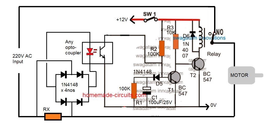
Here, a straightforward delay ON timer circuit is created using the two transistors and related parts. Because C1 first grounds the base drive of T1 arriving via R2 while C1 charges, when SW1 is turned on, the transistor T1 stays turned off.

As a result, the relay and T2 remain turned on. The pump motor is turned on by the relay's N/O. The motor is permitted to operate for a certain amount of time based on the number of C1. The motor operates unloaded with a comparatively low current flowing through RX in the event that there is no water. The opto-coupler LED switch remains off as a result of RX's inability to generate sufficient electrical potential across itself. This permits C1 to fully charge without interference throughout the allotted time period.

T1 turns ON immediately as C1 is completely charged, which turns T2 and the relay OFF. In order to prevent a dry run, the motor is ultimately turned off.

In contrast, if the motor receives a regular supply of water and starts pushing it routinely, the motor is immediately loaded, increasing the amount of current it uses.

This generates enough voltage across the resistor Rx, according to its predicted value, to turn on the opto-coupler's LED. The delay ON timer is turned off and C1 is prevented from charging after the opto is turned on. For as long as there is water available, the motor can keep trying to function thanks to the relay's continued supply of 220V.

You'll also like:

  • 1.  How to Make a Office Call Bell Network Circuit with LED Monitor
  • 2.  How to Make Logic Inverter, Buffer Gates using BJTs
  • 3.  Sound Operated Music Bell
  • 4.  Simple Melody Tone Generator Circuit
  • 5.  Simplest Transistor Running Light Circuit for Christmas Lighting Decoration
  • 6.  Automatic Central Heating Controller Circuit

About Admin

Hey friends, Thanks a bunch for stopping by this site! I am an engineer with a Bachelor of Engineering in Electronics and Telecommunication. One of my passions is gathering information from all sorts of electronics books and tutorials. I then take that information and compile it into a language that is super easy to understand. My goal is to make those complex electronics circuit concepts and technical terms much more accessible for all the new and budding electronics engineers out there. I can also design customized circuit diagrams as required by the users.
If you have any questions related to this field, please do not hesitate to drop a comment! I am always here and ready to help you out with any queries you might have. I cannot wait to hear from you!

Reader Interactions

Leave a Reply Cancel reply

Your email address will not be published. Required fields are marked *

Primary Sidebar

Categories

  • 3 Phase (4)
  • 8051 Microcontroller (1)
  • Arduino (11)
  • Audio and Amplifier (102)
  • Automation (8)
  • Battery Chargers (64)
  • Bicycle Projects (4)
  • Car and Motorcycle Projects (39)
  • Datasheets (10)
  • DIY Projects (5)
  • Electrical (15)
  • Free Energy (6)
  • Games Projects (2)
  • High Voltage (14)
  • Hobby Projects (30)
  • Household Circuits (2)
  • IC 555 Circuits (4)
  • Ignition Circuits (2)
  • Indicators (50)
  • Infrared (6)
  • Inverter Circuits (29)
  • Lights and Lamps (97)
  • Medical (8)
  • Meter and Tester Circuits (38)
  • Motor Driver (17)
  • New Circuits (56)
  • Oscillators (30)
  • Pets and Pests (5)
  • Power supply (81)
  • Protection Circuits (25)
  • PWM (8)
  • Remote Control (20)
  • Security and Alarm Circuit (48)
  • Sensors and Detectors (66)
  • Signal Processor (23)
  • Solar Controller Circuits (61)
  • SSR (3)
  • Temperature Controller (20)
  • Timer (25)
  • Transformerless (7)
  • Transmitters (12)
  • Tutorials (45)
  • UPS (2)
  • Voltage Regulators (57)
  • Water Sensor and Controller (29)
  • Home
  • Privacy Policy
  • Contact
  • Disclaimer
  • Copyright

© 2025 · Making Easy Circuits