• Skip to main content
  • Skip to primary sidebar

Making Easy Circuits

Learn and build electronic circuits

You are here: Home / Timer / Dark Room Timer Circuit

Dark Room Timer Circuit

Last Updated on May 15, 2020 by Admin Leave a Comment

Working in a darkroom is always fraught with problems. You surely know Murphys Law of; but Let’s not go into that here.

Suffice it to say that normal lights cannot be used in a darkroom when photographs are being developed not even if you drop your glasses!

The dark room timer circuit here is a simple, inexpensive design for a darkroom torch (or light) that can be mounted in a case small enough to fit into your pocket even with a 9 V battery included.

It gives enough light for note-taking or finding this or that in a darkroom, but the light is emitted by three special yellow LEDs which can safely be used near black/white or colour paper.

Red LEDs are used for orthochromatic material (we had to look it up too, it means giving correct relative intensity to colours in photography'!). An energy saving circuit is included that automatically switches the lamp off when the ambient light is above a certain level.

How it Works

The diagram for the circuit makes it look like a mini power supply.

Dark Room Timer Circuit

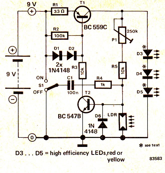
When the circuit is switched 'on' with S1 T2 conducts and provides, in turn, a base drive current to transistor T1.

This transistor then supplies the base current for T2 via R5 and P1.

Switching S1 off causes C1 to deliver a negative pulse to the base of T2 and this transistor then stops conducting.

T1 also stops conducting and the LEDs go out. The energy saving circuitry requires the addition of just one component, the LDR.

When enough light falls on it the LDR's resistance causes T2 to switch off and extinguish the LEDs.

The light level at which this happens is set by means of preset P1 Q LEDs D3 . . . D5 must be high efficiency types and are either red or yellow depending on what sort of photographic paper is used.

There are various high intensity LEDs available, although the light intensity level can also be changed by varying the current flow through T1 (by substituting another value of resistor for R1 ).

With the values stated about 20 mA flows through the LEDs and, seeing as the current consumption when the LEDs are off is only a few nA, the 9 V battery should last quite a while.

Finally it is important to remember that some types of photographic paper are sensitive to all colours, including red and yellow, so check this before using the lamp.

You'll also like:

  • 1.  How to Build a Aquarium Fish Feeder Timer Controller Circuit
  • 2.  Simple Delay ON Timer Circuit using Two BC547 Tansistors
  • 3.  How to Build a Reverse Forward Motor Timer Circuit for Incubator Mechanism
  • 4.  How to Build a Long Duration Timer Circuit Using Transistors
  • 5.  Simple Dark Room Timer Circuit for Photographers
  • 6.  Universal Digital, Programmable Timers Circuits

Tagged With: Timer

About Admin

Hey friends, Thanks a bunch for stopping by this site! I am an engineer with a Bachelor of Engineering in Electronics and Telecommunication. One of my passions is gathering information from all sorts of electronics books and tutorials. I then take that information and compile it into a language that is super easy to understand. My goal is to make those complex electronics circuit concepts and technical terms much more accessible for all the new and budding electronics engineers out there. I can also design customized circuit diagrams as required by the users.
If you have any questions related to this field, please do not hesitate to drop a comment! I am always here and ready to help you out with any queries you might have. I cannot wait to hear from you!

Reader Interactions

Leave a Reply Cancel reply

Your email address will not be published. Required fields are marked *

Primary Sidebar

Categories

  • 3 Phase (4)
  • 8051 Microcontroller (1)
  • Arduino (11)
  • Audio and Amplifier (102)
  • Automation (8)
  • Battery Chargers (64)
  • Bicycle Projects (4)
  • Car and Motorcycle Projects (39)
  • Datasheets (10)
  • DIY Projects (5)
  • Electrical (15)
  • Free Energy (6)
  • Games Projects (2)
  • High Voltage (14)
  • Hobby Projects (30)
  • Household Circuits (2)
  • IC 555 Circuits (5)
  • Ignition Circuits (2)
  • Indicators (50)
  • Infrared (6)
  • Inverter Circuits (29)
  • Lights and Lamps (97)
  • Medical (8)
  • Meter and Tester Circuits (38)
  • Motor Driver (17)
  • New Circuits (56)
  • Oscillators (30)
  • Pets and Pests (5)
  • Power supply (80)
  • Protection Circuits (25)
  • PWM (9)
  • Remote Control (20)
  • Security and Alarm Circuit (48)
  • Sensors and Detectors (66)
  • Signal Processor (23)
  • Solar Controller Circuits (62)
  • SSR (3)
  • Temperature Controller (20)
  • Timer (25)
  • Transformerless (7)
  • Transmitters (12)
  • Tutorials (45)
  • UPS (2)
  • Voltage Regulators (57)
  • Water Sensor and Controller (29)
  • Home
  • Privacy Policy
  • Contact
  • Disclaimer
  • Copyright

© 2025 · Making Easy Circuits