In one of our projects we required several matched silicon diodes for accomplishing a perfectly balanced modulation design.
We could easily construct it through a 9 V battery for the supply, two precision resistors, a digital voltmeter, as depicted in the following diagram.

The two 2.2 k resistors, namely R1 and R2, must be a matched pair. You must remember that any rated value, a 5% unit can deviate as much as +/- 110 ohms. Their true resistances aren’t so important as long as they have the same value.
Searching for the pair of resistors isn’t a tough job. You may collect a dozed of 2.2 k resistors and carefully review each value using a digital ohmmeter. Pair the two closest values for R1 and R2.
To use the diode matching circuit, connect a diode to each pair of test probes and fix the DVM to its most sensitive DC-voltage range. This must be done if the meter doesn’t have auto-ranging feature.
The reading on the meter will show the disparity in the forward voltage-drop of the two diodes in millivolts.
It must be noted that each diode should be allowed to revert to room temperature after handling, prior to taking any reading. Just in case, hold each diode for a while and observer the meter change as they get warm from your palm heat.
Improved Diode Pairing Circuit
If you need a more dynamic testing method, you could try to build the diode matching circuit shown in Figure 2 below. The standard circuit is identical to the previous one. The only difference is is the inclusion of a variable resistor R4. This component allows you to regulate the current via the diodes.
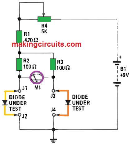
This permits you to compare the two diodes’ forward voltage-drop as the current flow is differentiated from less than 1 mA to above 7 mA.
If the voltage alters slightly over the current range, the two diodes are well-matched in their forward voltage curve.
Resistors R1 and R2 must be equated in the same method as in the first circuit.
Oscilloscope-Based Matching Circuit
Our last diode-matching circuit, as shown in Figure 3 below, permits you to observe the forward conduction curve of both diodes at the same time on an oscilloscope.
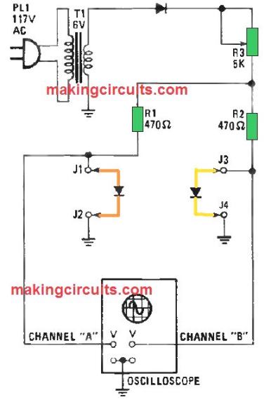
Using a 6 V transformer (T1) and diode D1 supplies a pulsed positive voltage to the two diodes through a 5000 Ω potentiometer and two matched 470 Ω resistors.
The scope should have dual vertical inputs to connect to each of the diodes under test. The scope’s vertical amplifiers can be deployed either the alternate or chopped mode to display both waveforms at the same time.
Setting the scope up for the dual-waveform circuit is simple. Firstly, set the gain of both vertical amplifiers to 0.2 V per division.
Then, insert the vertical-mode switch to either the chopped or alternate setting. After that, configure the horizontal sweep to 2 ms per division.
Then, set the scope’s trigger to generate a flatline and regulate the trace to each vertical input to superimpose and create a single line at the scope display’s center.
Finally, connect the scope to the test circuit, re-configure the trigger for a steady display and if the two diodes are a pair, two waveforms which are identical will appear as a single trace. Resistor R3 sets the diode’s forward current and can be regulated when testing.
Leave a Reply