• Skip to main content
  • Skip to primary sidebar

Making Easy Circuits

Learn and build electronic circuits

You are here: Home / New Circuits / Discotheque Music Level Indicator Circuit

Discotheque Music Level Indicator Circuit

Last Updated on November 27, 2024 by Admin 3 Comments

This is a novel music level indicator, ideally suitable for using in a place like discotheque. This indicator is made of eight columns of eight LEDs are being placed at equal distance, so that it looks like a star. The corresponding LEDs in the eight column form concentric circles as shown in the following figure.

figure 1b

The higher the sound level, there are more circles light – resulting into a star-alike pattern with constantly changing brightness.

PLEASE COMBINE THE TWO IMAGES BELOW TO COMPLETE THE FULL CIRCUIT SCHEMATIC OF THE PROPOSED DISCOTHEQUE MUSIC LEVEL EFFECT GENERATOR CIRCUIT

figure1 1
figure2 2

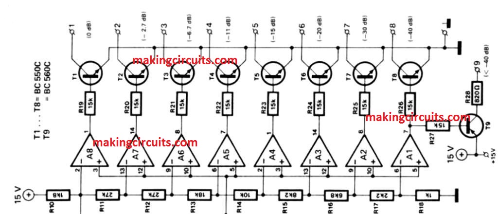
As depicted in the first figure, the eight LEDs in anyone of the eight circles are joined in series. Transistor in the above circuit schematic drives each of these series chains, for instance T1 to T8.

It is not required to drop the resistors: over 1.8v per LED is provided by the positive supply voltage – this voltage is perfect for LEDs to function properly.

How the Circuit Works

Differential amplifiers, i.e. A1 to A8 drives the Transistors T1 to T8 : the amplifiers compare the direct voltage across C2 and the direct voltage is dependent on the audio. C2 is buffered by A12, with the potential which is determined by D11 and from R11 up to R18. When the result of the comparison comes positive, the associated driver transistor is being turned on, as well as the appropriate circle of LEDs. D4 which is the LED in the centre is driven by T9 and the light only gets turned on when the sound level is significantly less.

The direct voltage which runs across C2 results from a full-wave rectification in A10 , as well as A11 of the input signal only after it is amplified in A9. For saturation, the sensitivity of the input value mist be about 600mV which is required to turn on all 64 LED lights. However, the number can be increased by decreasing the value of R2.

The speed with which variation in music level is displayed, relies on the value of C2: if the value is 10µF, there is a slow change in light patterns. On the other hand, when the capacitor is omitted, it readily reacts to variant sound changes.

PCB Designs

PCB design
PCB for LED board

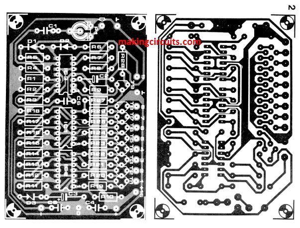
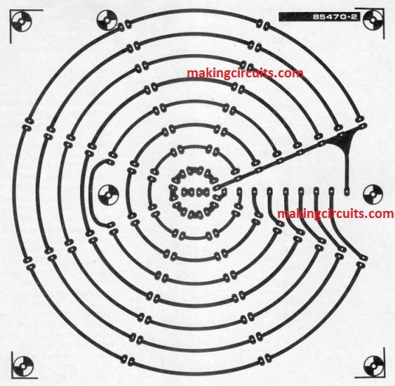
The discotheque music level indicator circuit is created on two printed circuit boards as indicated above. The LED board as shown above doesn’t comprise of a component layout since it didn’t look aesthetically attractive. One can fit the two boards together with the use of spacers: exact holes are being given for this in a pattern which makes sure that all the 11 terminals for interconnections on the board remains opposite to one another.

You'll also like:

  • 1.  Build this Hartley Oscillator Circuit
  • 2.  How to Build a LM317 as a Variable Voltage Regulator and Variable Current Regulator
  • 3.  Simple Melody Tone Generator Circuit
  • 4.  Dry Run Protection for Motor using Reed Relay Switch
  • 5.  Simplest Transistor Running Light Circuit for Christmas Lighting Decoration
  • 6.  How to make a Temperature Triggered DC Fan Speed Controller Circuit

About Admin

Hey friends, Thanks a bunch for stopping by this site! I am an engineer with a Bachelor of Engineering in Electronics and Telecommunication. One of my passions is gathering information from all sorts of electronics books and tutorials. I then take that information and compile it into a language that is super easy to understand. My goal is to make those complex electronics circuit concepts and technical terms much more accessible for all the new and budding electronics engineers out there. I can also design customized circuit diagrams as required by the users.
If you have any questions related to this field, please do not hesitate to drop a comment! I am always here and ready to help you out with any queries you might have. I cannot wait to hear from you!

Reader Interactions

Comments

  1. Tatsuya says

    February 26, 2023 at 8:24 am

    also can i have a high res image i want to try this for my college project

    Reply
  2. Tatsuya says

    February 26, 2023 at 8:18 am

    hi can you connect the two diagrams and label the Audio input

    Reply
    • admin says

      March 6, 2023 at 11:41 am

      There are only two connections to be made between the upper diagram and the lower diagram, also make sure the positive and the negative supplies are connected for both the diagrams.

      Audio input is across P1 preset

      Reply

Leave a Reply Cancel reply

Your email address will not be published. Required fields are marked *

Primary Sidebar

Categories

  • 3 Phase (4)
  • 8051 Microcontroller (1)
  • Arduino (11)
  • Audio and Amplifier (102)
  • Automation (8)
  • Battery Chargers (64)
  • Bicycle Projects (4)
  • Car and Motorcycle Projects (39)
  • Datasheets (10)
  • DIY Projects (5)
  • Electrical (15)
  • Free Energy (6)
  • Games Projects (2)
  • High Voltage (14)
  • Hobby Projects (30)
  • Household Circuits (2)
  • IC 555 Circuits (5)
  • Ignition Circuits (2)
  • Indicators (50)
  • Infrared (6)
  • Inverter Circuits (29)
  • Lights and Lamps (97)
  • Medical (8)
  • Meter and Tester Circuits (38)
  • Motor Driver (17)
  • New Circuits (56)
  • Oscillators (30)
  • Pets and Pests (5)
  • Power supply (80)
  • Protection Circuits (25)
  • PWM (9)
  • Remote Control (20)
  • Security and Alarm Circuit (48)
  • Sensors and Detectors (66)
  • Signal Processor (23)
  • Solar Controller Circuits (62)
  • SSR (3)
  • Temperature Controller (20)
  • Timer (25)
  • Transformerless (7)
  • Transmitters (12)
  • Tutorials (45)
  • UPS (2)
  • Voltage Regulators (57)
  • Water Sensor and Controller (29)
  • Home
  • Privacy Policy
  • Contact
  • Disclaimer
  • Copyright

© 2025 · Making Easy Circuits