• Skip to main content
  • Skip to primary sidebar

Making Easy Circuits

Learn and build electronic circuits

You are here: Home / Security and Alarm Circuit / Dog Barking Sound Simulator Circuit

Dog Barking Sound Simulator Circuit

Last Updated on April 3, 2020 by Admin 4 Comments

In this post we learn how to make a simple dog barking sound generator, which will simulate an exact dog bark sound through an electronic circuit.

The music synthesizer was the inspiration for ideas while making the circuit to simulate a dog barking sound.

The S2 push button is pressed to raise the frequency of the VCO or voltage-controlled oscillator A1-A2 from 0 Hz to a value between 100-1000 Hz, which can be preset, in the span of about 1/8 of a second.

How the Circuit Works

A5-A6 is a band-pass filter with its center frequency at the highest frequency of the VCO, through which the signal from the VCO is passed. T1, a voltage-controlled amplifier or VCA, suppresses the sound due to the single pulse from the VCO when S2 is open.

A monostable relaxation oscillator is formed by the gates N1 and N2. On closing S2, the capacitor C2 is charged by the short pulse that formed at the output of N2. R3 causes the shape of the pulse to take the form as shown in Figure 1.

dog barking sim circuit

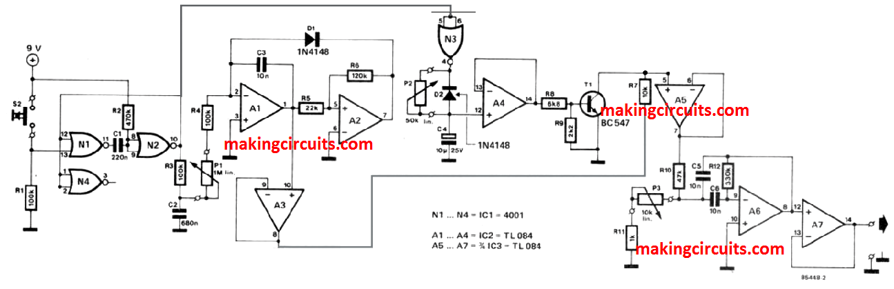
You can also infer from the figure that the output frequency of the VCO is determined by this pulse. The highest frequency is set by the potentiometer P1 - a low value emulates a deep bark while a higher value produces a yelp-like sound.

How to Setup the Dog Bark Sound

Like C2, C4 also helps to mold the shape of the pulse to the VCA. The transistor acts as an electronic potentiometer in that it functions as a voltage-controlled resistor.

The function of the P2 adjusting potentiometer is to affect the manner of decay of the tone after the release of the switch.

If the sound is cut off too fast or draws on too long, it would not sound authentic enough.

Tinkering with the circuit values will even allow you to create different kinds of barks. P3 is used to fix the center frequency of the band-pass filter A5-A6, which too will require some experimentation to get correct.

You can connect this dog barking sound simulator circuit output to a power amplifier and use it as an alarm system to scare off burglars.
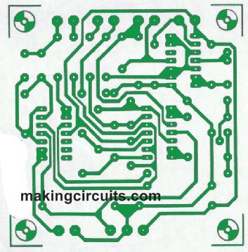
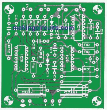
Full PCB Design

Also, you should know that you will not find a ready-made printed circuit board for the above explained dog bark sound simulator circuit.
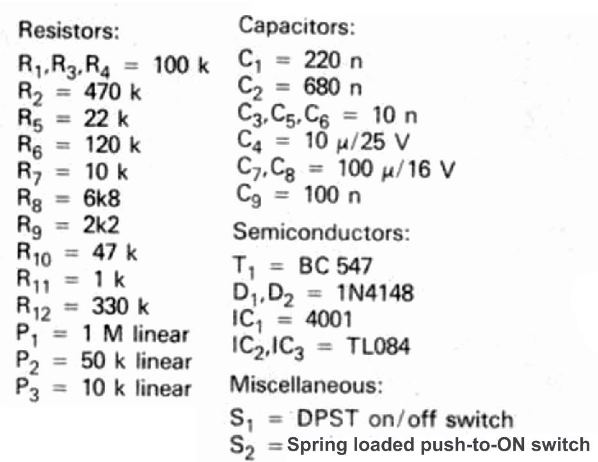
track side dog bark
comp layout dog bark

Complete Parts List

parts list

You'll also like:

  • 1.  Ultrasonic Alarm Circuit
  • 2.  Fridge Alarm Circuit
  • 3.  Small Fence Charger Circuit using a Single Transistor
  • 4.  Simple Smoke Detector Circuit
  • 5.  How to Build a RF Signal Jammer Circuit
  • 6.  Anti-Burglar Home Lighting Circuit

About Admin

Hey friends, Thanks a bunch for stopping by this site! I am an engineer with a Bachelor of Engineering in Electronics and Telecommunication. One of my passions is gathering information from all sorts of electronics books and tutorials. I then take that information and compile it into a language that is super easy to understand. My goal is to make those complex electronics circuit concepts and technical terms much more accessible for all the new and budding electronics engineers out there. I can also design customized circuit diagrams as required by the users.
If you have any questions related to this field, please do not hesitate to drop a comment! I am always here and ready to help you out with any queries you might have. I cannot wait to hear from you!

Reader Interactions

Comments

  1. Anand Kumar Mallik says

    November 1, 2022 at 12:55 pm

    I want to get one full set( i.e. PCB and components). Kindly let me know the cost of the same.

    Reply
    • admin says

      November 7, 2022 at 7:17 pm

      Sorry, unfortunately the above project is not available ready made….

      Reply
  2. Anand Kumar Mallik says

    September 24, 2022 at 5:10 pm

    will this circuit work well and give the actual sound of barking of german shepherd dog
    if you asure me then help me with pcb and it’s components. kindly inform me the full cost.
    waiting for your reply.

    Reply
    • admin says

      October 2, 2022 at 9:54 am

      It will work and give the actual sound of dog barking, only if it is built correctly

      Reply

Leave a Reply Cancel reply

Your email address will not be published. Required fields are marked *

Primary Sidebar

Categories

  • 3 Phase (4)
  • 8051 Microcontroller (1)
  • Arduino (11)
  • Audio and Amplifier (102)
  • Automation (8)
  • Battery Chargers (64)
  • Bicycle Projects (4)
  • Car and Motorcycle Projects (39)
  • Datasheets (10)
  • DIY Projects (5)
  • Electrical (15)
  • Free Energy (6)
  • Games Projects (2)
  • High Voltage (14)
  • Hobby Projects (30)
  • Household Circuits (2)
  • IC 555 Circuits (5)
  • Ignition Circuits (2)
  • Indicators (50)
  • Infrared (6)
  • Inverter Circuits (29)
  • Lights and Lamps (97)
  • Medical (8)
  • Meter and Tester Circuits (38)
  • Motor Driver (17)
  • New Circuits (56)
  • Oscillators (30)
  • Pets and Pests (5)
  • Power supply (80)
  • Protection Circuits (25)
  • PWM (9)
  • Remote Control (20)
  • Security and Alarm Circuit (48)
  • Sensors and Detectors (66)
  • Signal Processor (23)
  • Solar Controller Circuits (62)
  • SSR (3)
  • Temperature Controller (20)
  • Timer (25)
  • Transformerless (7)
  • Transmitters (12)
  • Tutorials (45)
  • UPS (2)
  • Voltage Regulators (57)
  • Water Sensor and Controller (29)
  • Home
  • Privacy Policy
  • Contact
  • Disclaimer
  • Copyright

© 2025 · Making Easy Circuits