This article will teach you how to create an electromagnetic levitation circuit that can simulate an anti-gravity effect by keeping an iron object drawn above the ground by an electromagnet to ensure that it doesn't adhere to it but instead floats between the ground and the electromagnet tip.
Fundamental Operational Principle
An LED and LDR combo is used such that the LED beam illuminates the LDR after passing just beneath the electromagnet. In this case, the electromagnet continues to operate and its electromagnetic power is active throughout the duration as the LDR is lit.
An iron item positioned underneath the electromagnet begins to be drawn in its direction, however during the process, the LED ray that reaches the LDR is cut off, turning the electromagnet off.
This causes the iron item to start falling, but it also starts to move out of the way of the LED beam so that the light may get to the LDR.
This condition turns the electromagnet back on, causing the iron object to begin to attract towards it once more. This up-down cycle is repeated quickly, resulting in an environment in which the iron item is neither fully collapsed to the ground nor fully tugged by the electromagnet. It creates the illusion of an anti-gravity levitation impact by keeping the iron item floating in suspended state, maybe a few millimeters under the electromagnet.
How You can Make it
The simplest way to construct the levitation arrangement is to use wooden building blocks and frame them as follows:

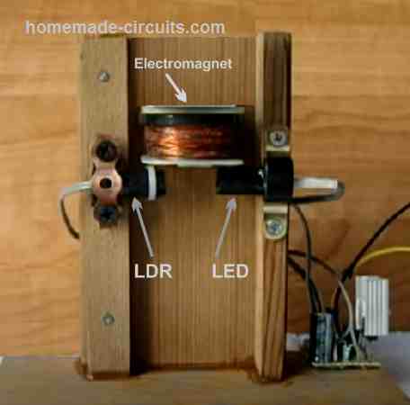
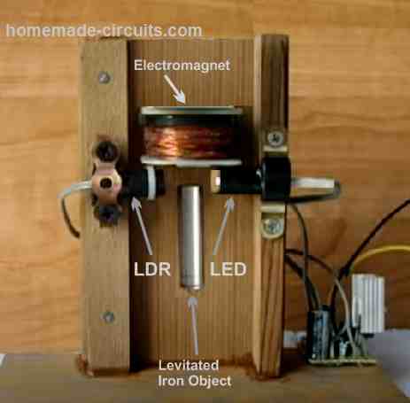
The electromagnet is mounted in the upper center section of the wooden buildings in this configuration, and the LED and LDR are placed facing each other above the nearby perpendicular wooden structures, directly underneath the electromagnet.
To guarantee that only the LED light ray penetrates and lights the LDR tube while ensuring no other natural light from the outside may reach the LDR, it is crucial that the LED and the LDR be positioned inside opaque plastic tubes.
The LED turns on and strikes the LDR when the electromagnetic levitation circuit is switched on, turning on the electromagnet.
When an iron object comes close to an electromagnet that has been turned on, the item will be drawn in its direction.
Iron objects, nonetheless have a tendency to obstruct the LED beam's path to the LDR during this procedure. The electromagnet will be switched off immediately as a result. When this occurs, the iron item will likely fall, however it will do so by moving away from the LED ray that illuminates the LDR and turns the electromagnet back on. As seen in the next image, the iron item will continue to hang slightly beneath the magnetic due to its quick ON/OFF action, giving the appearance of a real levitation or anti-gravity effect.

Working of the Circuit
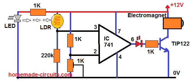
The following figure shows the circuit for the levitation system:

The whole system is constructed around a single IC 741 that is set up as a comparator, as we observe, and there are only a few parts in the schematic.
The preset 1k is used to fix the op amp's pin #2 with a steady reference voltage. Considering the LDR toggling is either ON or OFF, this reference voltage is not particularly important.
As perceived in our earlier constructing setup of the device, the LED light is visible concentrated on the LDR.
The op amp's pin #3 voltage increases over the pin #2 reference potential, which is controlled by the 1k setting, as a result of the light's resistance decreasing to a considerably smaller value while it is centered on the LDR.
As a result, the op amp's output stays high, keeping the magnetic turned on.
The iron item tries to stop the LED beams from reaching the LDR when it is drawn in the direction of the magnetic, as was covered in the preceding paragraphs.
The pin #3 potential falls below the pin #2 reference potential, which then increases beyond the pin #3 voltage, as a result. This causes the op amp's pin #6 output to cut off, turning off the driver transistor and the electromagnet in the process.
This immediate magnetic switching off tends to drop the iron item, which makes the LDR lighted by the LDR beam once again. This causes the op amp output to return back to high, turning the electromagnet back on.
The iron item is being pulled and dropped at a very rapid pace, giving the impression that it is levitating and hanging in suspended position because of the anti-gravity effect, while the item seems to be stationary underneath the electromagnet.
How the Electromagnet Is Made
Any sturdy iron bolt may be used to wind 120 grams of 28 SWG super enameled wire to create an electromagnet. prior to you begin winding the coil, ensure that to wrap the iron bolt with a few layers of protective PVC tape.
You may easily take out the relay coil from any old 12V, 30 amp relay in the event you are unsuccessful to construct the electromagnet described above.
Benefits of LED/LDR Sensor Technology
Numerous magnetic levitation circuits that employ an infrared photodiode as the sensor are accessible online. Newcomer aficionados might find it difficult to choose the right photodiode, and occasionally there can arise problems with the photodiode's output.
It is more beneficial to use an LDR/LED combo since they are readily accessible and do not have rigid requirements. You only need to select a little 3.3 V white LED and almost any tiny LDR to be operating.
Employing an LED also has the benefit of illuminating the space directly beneath the electromagnet, which produces an intriguing effect on the ascended iron item.
Leave a Reply