• Skip to main content
  • Skip to primary sidebar

Making Easy Circuits

Learn and build electronic circuits

You are here: Home / Security and Alarm Circuit / Simple Electronic Siren Circuit

Simple Electronic Siren Circuit

Last Updated on November 17, 2024 by Admin Leave a Comment

This simple electronic siren circuit project aims to explain designing a simple circuit for an electronic siren. It is built on a single chip – CD4011 (IC1). In order to make this work, we need four NAND Gates with 2-input of IC1. Both the gates will be configured to manage high and low frequency oscillator.

The conduction D2 Diode in the circuit responds when there is high output from low frequency oscillator and further enables high frequency oscillator. To change the speed of the oscillator, the value of C3 capacitor can be raised to 8µF.

To tone the changer components, the C1 Capacitor and R1 Resistor are used in this design. Also, in order to let the D1 Diode operate at its full output we have used C2 capacitor. The T1 Transistor in the circuit is used as speaker driver.

Following is a circuit diagram of the electronic siren:

simple electronic siren circuit

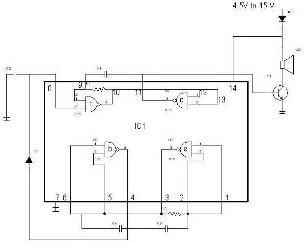
Electronic Siren Circuit Diagram

Here lists below the components that you need to design the project:
Resistors Capacitors Semiconductors Others
R1 = 150 KΩ C1 = 0.015 µF IC1 = CD4011 LS1 = 8Ω speaker
R2 = 500 KΩ C2 = 0.22 µF T1 = BEL187
C3 = 0.5 µF D1 = 1N4148
C4 = 10 pF D2 = 1N4001
NOTE: All resistors should be ¼ watt and ± 5% Carbon.

Siren Circuit using IC 4093

The circuit shown here, despite the frugality, can make quite some noise. This is made possible by the use of T1, an n-channel MOSFET, that works the loudspeaker.

siren circuit

CMOS logic circuits can be used to directly drive the MOSFET. The type used here has an output resistance or drain-source of just 3Ω. On top of that, the drain current can get upto 1.7 A, with the maximum drain-source voltage being 40 V. This does not depend on the polarity of the applied voltage, as there is internal diode protection for the device.

The MOSFET, thus rendered literally undamageable, can be connected to a loudspeaker.

You can control the circuit with a computer. This can be done by making the ENABLE input logic high. Of course, you can use a switch too instead of a computer. On encountering a high input at pin 5 of gate N2, the Schmitt trigger N1 produces pulses that causes N2 to oscillate. The output of N2 acts on the MOSFET, via the buffer N3. P1 is used to control the frequency of N2.

Alarm systems are a great application for this siren circuit.

IC 7400 Siren Circuit

The IC 7400 siren circuit comprises of a couple of oscillators which will produce the tones.

FIG1 4

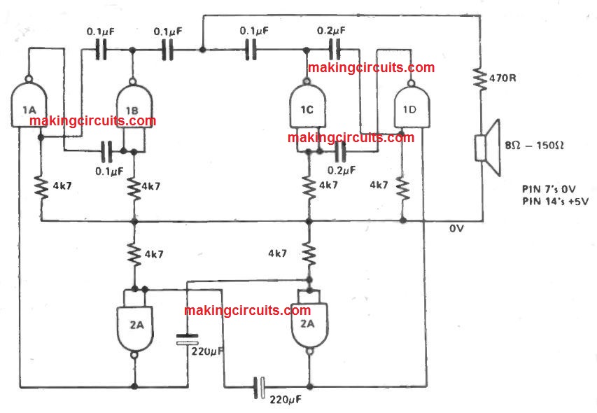
A third oscillator is employed to switch the remaining tones on and off alternately, supplying the two tone output.

By modifying the capacitor values different tones could be generated.

You'll also like:

  • 1.  Vibration Activated Alarm Circuit
  • 2.  High Voltage Alarm Circuit
  • 3.  How to Make a Power ON Alarm with Auto OFF Circuit
  • 4.  Battery Low Voltage Alarm Circuit using NAND Gates
  • 5.  Single IC High Power Siren Horn Circuit
  • 6.  Dog Barking Sound Simulator Circuit

About Admin

Hey friends, Thanks a bunch for stopping by this site! I am an engineer with a Bachelor of Engineering in Electronics and Telecommunication. One of my passions is gathering information from all sorts of electronics books and tutorials. I then take that information and compile it into a language that is super easy to understand. My goal is to make those complex electronics circuit concepts and technical terms much more accessible for all the new and budding electronics engineers out there. I can also design customized circuit diagrams as required by the users.
If you have any questions related to this field, please do not hesitate to drop a comment! I am always here and ready to help you out with any queries you might have. I cannot wait to hear from you!

Reader Interactions

Leave a Reply Cancel reply

Your email address will not be published. Required fields are marked *

Primary Sidebar

Categories

  • 3 Phase (4)
  • 8051 Microcontroller (1)
  • Arduino (11)
  • Audio and Amplifier (102)
  • Automation (8)
  • Battery Chargers (64)
  • Bicycle Projects (4)
  • Car and Motorcycle Projects (39)
  • Datasheets (10)
  • DIY Projects (5)
  • Electrical (15)
  • Free Energy (6)
  • Games Projects (2)
  • High Voltage (14)
  • Hobby Projects (30)
  • Household Circuits (2)
  • IC 555 Circuits (5)
  • Ignition Circuits (2)
  • Indicators (50)
  • Infrared (6)
  • Inverter Circuits (29)
  • Lights and Lamps (97)
  • Medical (8)
  • Meter and Tester Circuits (38)
  • Motor Driver (17)
  • New Circuits (56)
  • Oscillators (30)
  • Pets and Pests (5)
  • Power supply (80)
  • Protection Circuits (25)
  • PWM (9)
  • Remote Control (20)
  • Security and Alarm Circuit (48)
  • Sensors and Detectors (66)
  • Signal Processor (23)
  • Solar Controller Circuits (62)
  • SSR (3)
  • Temperature Controller (20)
  • Timer (25)
  • Transformerless (7)
  • Transmitters (12)
  • Tutorials (45)
  • UPS (2)
  • Voltage Regulators (57)
  • Water Sensor and Controller (29)
  • Home
  • Privacy Policy
  • Contact
  • Disclaimer
  • Copyright

© 2025 · Making Easy Circuits