This highly versatile, reliable transformerless power supply features a stable, adjustable DC output with a relatively high current of around 110 mA.
The pulsating direct voltage provided by rectifier D1—D4 has a peak value of 310 V. This voltage is given to the drain of power MOSFET T1 through limiting resistor R9.
How it Works
A control circuit makes certain that the MOSFET exclusively switches at the time of the brief periods right before and after the input AC moves through zero crossing line. Over these periods the brief magnitude of the pulsing DC doesn’t go over 5 V.
During precisely the same brief moments filtering capacitor C2 is charged: in the remaining times it gives the output current. As a result, this capacitor features a extremely high value: 10000 pF. The pulses of the load current carry a maximum value, it just for a short instant, may be around 4 Amps.
The output voltage stability is basically depends on the connected load. The output current could be relatively high at around 110 mA. The power for the control circuit is given by resistor R2, capacitor C1, and diodes D5 and D6.
The control circuit is actually a kind of window comparator crafted through three op amps. Appropriate calibration of the control circuit is as a result extremely important.
Before supplying the mains AC during the first testing, adjust the P1 to the center of its travel and flip P2 to ensure that its slider arm is at ground level. Next attach the mains AC input and check the working voltage of the circuit.
After this, attach a voltmeter (10 V dc range) across the output and fine-tune P2 until the meter reading slightly starts changing.
Lastly, fine-tune P1 for a reading on the meter of 4.8 V to 5 V. This circuit may not be suitable for all types of loads. It is apparent that it should not be utilized with devices that requires electrical isolation from the mains AC.
Likewise, this high current MOSFET transformerless power supply design may not be appropriate for with loads or devices that may be sensitive mains AC spikes and interference. It is, on the other hand, extremely acceptable for loads that has no accommodation for a mains transformer.
The proposed high current variable transformerless power supply circuit must mainly be used for supplying devices that may be perfectly covered, well-insulated inside a plastic box.
Any load operated through the explained design must not be attached some other devices through wires. This sort of cable connections, if required, must be simply by an oplo-coupler.
Heat generated on transistor T1 and resistor R9 can be expected to be around 3 W. This means even if the circuit is installed inside a compact enclosure there may not be any kind of warming issues. While assembling this high current transformerless power supply circuit the standard safety measures strictly related to mains AC powered circuits must be followed without fail.
Warning! This high current transformerless circuit using MOSFET must be built and wired with utmost caution since the entire mains voltage exists on many different points
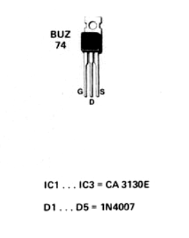
MOSFET and IC Details
Leave a Reply