Voltage drop suggests the decrease in voltage or voltage decline. Because of the existence of the impedance or passive components, you will see certain reduction in voltage as the current travels via the circuit.
Meaning , the power delivered from the voltage supply tends to get lowered as the current runs across the circuit. An excessive amount of voltage drop may lead to deterioration and poor functionality of the electrical and electronics equipment. Fundamentally, the voltage drop mathematics is implemented by Ohm’s law.
Voltage Drop in Direct Current Circuits
In DC circuits, the actual cause of voltage drop may be the resistance. For realizing the voltage drop in DC circuit, we are able to consider an illustration. Suppose a circuit that includes DC supply, A couple of resistors hooked up in series and a load.
At this point; each and every part of the circuit could have some resistance, they acquire and drop energy to certain extent.
However the determining aspect of the energy magnitude will be the natural attributes of the components. When you evaluate the voltage over the DC supply and very first resistor, you can see it can easily be lower than the supply voltage.
We are able to determine the power absorbed by each and every resistance by testing the voltage around specific resistors.
Whilst the current runs throughout the line starting from the DC supply towards the first resistor, certain energy may get dissipated because of the resistance offered by the conducting line.
In order to validate the voltage drop, Ohm’s law and Kirchhoff’s circuit law are widely-used as indicated below.
Ohm’s law is manifested by
V = R x I
- V → Voltage Drop (V)
- R → Electrical Resistance (Ω)
- I → Electrical Current (A)
For DC looped circuits, we likewise apply Kirchhoff’s circuit law for voltage drop calculation. It is done as follows:
Supply Voltage = Total of the voltage drop across every single element of the circuit.
Voltage Drop Calculation of a DC Power Line
In this article, let's take the illustration of 100 ft power line. Therefore, for just two lines, 2 × 100 ft. Let's consider electrical resistance be 1.02Ω/1000 ft and current be 10 A.
Electrical resistance = 1.02 / 1000 x 2 x 100
∴ Voltage Drop Vd = R x I = 0.204 Ω x 10 A = 2.04 V
Voltage Drop in Alternating Current Circuits
In AC circuits; in addition to Resistance (R), you will see a second resistance for the movement of current - Reactance (X) that includes XC and XL. The two X and R will resist current and the total of the two is known as Impedance (Z).
XC → Capacitive reactance
XL → Inductive reactanceZ = R +jX
The level of Z is determined by parameters like magnetic permeability, electrical isolating factors and the AC frequency.
Just like Ohm’s law in DC circuits, we can represent it as:E = Z x I
- E → Voltage Drop (V)
- Z → Electrical Impedance (Ω)
- I → Electrical Current (A)
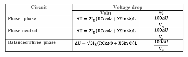
Voltage drop in alternating current circuits
- IB → Full load current (A)
- R → Resistance of the cable conductor (Ω/1000ft)
- L → Length of the cable (one side) (Kft)
- X → Inductive Reactance (Ω/1000f)
- Vn → Phase to neutral voltage
- Un → Phase to phase voltage
- Φ → Phase angle of load
Circular Mils and Voltage Drop Calculation
Circular mil in fact unit of area. It is put to use for mentioning the circular cross sectional area of the wire or conductor. The voltage drop applying mils can be written as:V = KPLI / A
L → Wire length (ft)
K → Specific Resistivity (Ω-circular mils/foot).
P → Phase constant = 2 intended for single phase = 1.732 for the purpose of three phase
I → Area of the wire (circular mils)
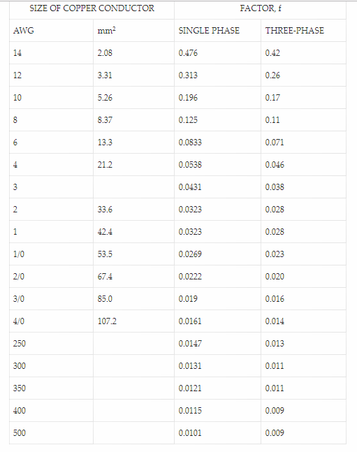
Voltage Drop Calculation of Copper Conductor through Table
The voltage drop of the copper wire (conductor) are accessible from the following data:
can we calculate the voltage drop across the circuit using the above formula?
Yes you can….