In this post we are going to research a basic LED tube light circuit which might be instantly changed with defective any 40 watt T17 fluorescent tubes and installed straight on the current fixture. Hence the circuit is suitable for almost all regular iron ballast fixture assemblies.
Since presented in the below diagram, standard fluorescent fixtures are comprised of two side connectors, a series iron core ballast and a complimenting series starter unit. Each one of these are usually cabled as demonstrated below over a long MS metal fixture. The florescent tube becomes fixed between the two spring loaded side connectors which have a number of inserted clips for controlling and hooking up the tube light end pinouts.

The starter is connected across one of the adjacent pair of end pins while the ballast is connected in series with the other adjacent pins of the side connectors.
The series outputs from the ballast and one of the connectors are lastly shut down for getting the mains AC voltage.
When AC is first turned on, the starter fires randomly and switches the tube in a flickering mode, which causes reverse high voltage EMFs to be produced by the ballast. This get rid of starts and ignites the tube internal gas and lights up the tube preventing the starter such that now the starter no longer performs current, rather the current is now carried out by means of the lighted tube internal gaseous path.
As soon as the tube is activated completely the choke or the ballast basically works like a current limiter for limiting a safe stipulated quantity of amps to the tube as per the resistance of the ballast coil. In good quality ballasts the resistance or the number of turns inside the ballast is going to be properly determined to reduce heat generation and make sure longer tube life.
In spite of this one big disadvantage with these regular iron core ballasts is the discharge of excessive heat while decreasing current to the tube, which means it is quite ineffective as far utility saving is involved.
LED tube lights much like T17 fluorescent have grown to be quite typical available in the market in these days however these come with their very own particular fixtures, and simply cannot be changed on the standard FTL fixtures.
Considering that the majority of homes have these regular iron core type fixtures fitted on their walls, obtaining an LED tube replacement which is instantly appropriate for these turns into extremely suitable and useful.
Within this submit we talk about an easy LEd tube light circuit which supplies all the good features of LED technology and yet is instantly replaceable over standard T17 FTL fixtures.
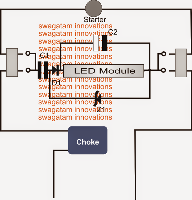
The circuit design could possibly be observed in the following diagram situated at the middle of fixture wiring and displays how the circuit configuration permits an immediate set up characteristic.
The circuit is a regular capacitive power supply which can be half wave rectified by D1 and filtered by C1.
The zener Z1 guarantees a continuing 180V DC across the linked LED module.
The LED module is practically nothing, but contains around 50 numbers of 1 watt LEDs in series end to end.
The present choke or the iron ballast is permitted to be in the wiring chain which now acts like a perfect surge suppressor so enabling enthralling the incoming current in-rush in the course of first turn on.
The starter in spite of this performs simply no part in the design and might be either taken away or its existence could be disregarded.
Changing Fluorescent Tubes to LEDs
Parts List
C1 = 105/400V
C2 = 10uF/400V
D1 = 1N4007
Z1 = 180V zener, 1 watt
LED Module = see text
Leave a Reply