Through this submit we talk about an efficient and valuable high current capacitive compact power supply making use of a dimmer switch gadget.
From one of my further articles I explained a high voltage transformerless power supply circuit that utilized a triac for managing the capacitive output, in spite of this considering that the idea required shorting the capacitive output by the triac the design undergone serious losses therefore lost a lot effectiveness in the course.
Any specific power supply exactly where a shunting of the output is required may lose performance as a result of the valuable power being put through the ground...which is an extremely crude procedure for attaining a voltage control.
The proper technique for accomplishing optimal efficiency is to do just the opposite, it is to discontinued power to the output the moment the output tends to go above the specific or the graded load voltage, instead of shunting the output V and I.
Obtaining an optimal current supply from a capacitive power supply is not easy simply because a capacitive power supply as we all be familiar with work effectively only provided that the output load voltage rating competes with the input voltage of the power supply, instance a capacitive power supply working at 220V will continue to work effectively provided that the load specs are likewise scored at 220V...otherwise the effectiveness of the supply will start dropping and lead to severe voltage and current drop across the connected load.
Consequently when a lower DC load is meant to be controlled from a 220 V capacitive power supply and a resistor is integrated as a simple or a less expensive option for reducing power, plenty of energy gets disposed of by means of heat and the system results in being not able to work with max effectiveness, the same takes place with a circuit that shunts output voltage for applying voltage regulation.
In the current design we utilize a dimmer switch which additionally uses a triac for managing voltage but rather of shunting power the circuit chops the AC into sections such that the normal voltage at the output turns into appropriate to the preferred load voltage.
Chopping the AC into wider or narrower sections according to the needed load potential permits the capacitor to engage in its complete performance due to the fact the excess power from it is merely stop rather than shunting or shorting to ground.
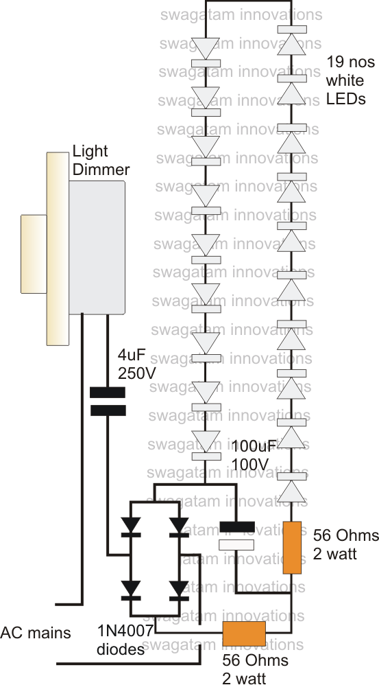
A pleasant illustration might be observed in the above diagram exactly where a dimmer switch could be noticed wired with a capacitive transformerless power supply circuit for operational a high current load for example a string of high watt LEDs.
As could be spotted the capacitor employed is a 4uF high value capacitor which can be scored to offer as much as 350mA of current when managed in its max effectiveness only provided that the load does not need to shunt or short the power.
The dimmer switch enables the whole high current to go through the capacitor but blocks the voltage by chopping the AC stage into determined sections.
The above function guarantees a full 350 mA to achieve the load yet reduce the harmful high voltage from the capacitor to the load to be able to stop the load from damage or over heating....the process confirms a perfect effective procedure of the offered high current transformerless power supply circuit.
Leave a Reply