The digital time clock discussed the following is a circuit which most electronic amateurs would like to generate.
Maybe you have found out about digital clocks produced from clock ICs for instance the popular LM8361, MM5387 etc however ICs may very well be nowadays quite disused and/or difficult to create.
The existing design is really a lot less difficult with no much less than their previously discussed competitors with regards to function and technical specs. Additionally there may be one added advantage involved in this digital clock circuit, it can be Duplex LED display model, that helps to minimize the quantity of connections and links across the IC1 (LM8560) as well as the LED display, permitting the configuration to be faster and easier.
Currently let's understand how the suggested digital clock circuit works:
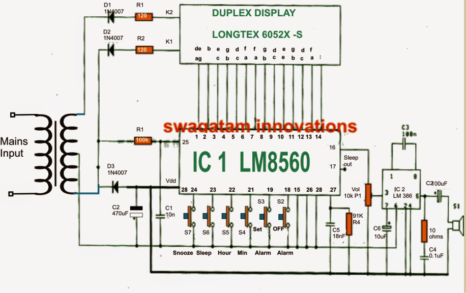
As could be noticed in the provided diagram the heart of the circuit is produced by the IC1 (LM8560),
that may be allocated with the following outputs terminals:
1. The output for driving the display Duplex Model numbers (pin 1-14)
2. The output for creating an alarm signal at pin 16.
3. The output alternative which might be applied for handling external electrical equipment by way of an in-built automatic timer.
The parts R1, C1 feature in the circuit that allows you to allow an input 50 Hz clock to pin25 of the IC.
The diodes D1, D2 are situated as rectifiers to serve as signal generators to the cathode of display number for creating an alternating operating of the display illumination regarding the input of IC1.
The alarm signal from pin 16 of IC1, is attached with a potentiometer P1(Volume) as well as further incorporated with pin 3 of IC2 (LM386) which designs the amplifier level for driving a loudspeaker in the course of alarm activations.
The P1 is protected with the intention to supply a good tuning choice for the alarm signal volume. In addition the signal from the "sleep" pinout from pin 17 can be used for handling almost every other most wanted prompt circuit.
The best way to set the time in this digital clock
1. S6 is utilized to set hours.
2. S4 is utilized to set minutes.
To set the alarm time the following switches should be employed:
1. S3 to hold down the time
2. S5 to set hours for the alarm.
3. S4 to set minutes for the alarmm.
The moment the previously discussed time limit by way of S4/S5 elapses, the alarm may commence ringing which might be ended by pressing switch S2 or in actual fact another switch out of the provided kinds.
The following switches can be used for handling an external device from the clock activates.
1. Originally you would like to continue switch S6 pressed
2. Next press S4 to set minutes.
3. Press switch S5 to set hours.
The output signal for the above discussed ON/OFF control of equipment could be gained from pin17 of the IC.
Making use of time dilation alarm to repeat alarm.
That allows you to make use of this feature for instance you should Repeat alarm or to lengthy for another nine minutes, you really should press switch S7.
Where do you find the duplex display? I can’t seem to find one
Try searching for:
dual 7 segment LED display module
Just ask me at my mail account
Can send pictures!
Hello Joy, I have some duplex displays. Still needed? Can send you pictures.
Johnboy
Well whenever. Thanks.
Hi,
I am looking for a circuit diagram copy of a Maplin 1970s clock kit.
Maplin Period Clock. BY 21.
Best regards.
Hi, sorry I do not have it at this moment!