Even in the ear of electrophonics, wah-wah box is still a very famous way of animating a guitar which normally sound so boring.
A guitar wah-wah pedal box is actually a high-Q low-pass or band-pass filter which transform the guitar sound imitating a human crying voice "wah-wah". This wah wah sound is varied and enhanced in many innovating ways depending on how the pedal is pressed at different pressure and angle by the guitarist.
A wah wah circuit can be designed in different ways. However, the former designers were based on transistorized double T-filters.
How the CircuitsWorks
The present design uses opamps and operational transconductance amplifiers or OTAs. It is even more complex, but even more efficient and trust-worthy.
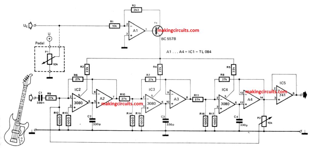
There are three pairs of opamps, each pair consists of an OTA and a buffer amplifier. The opamps, win conjunctions with capacitators C2, C3, and C4 form a low-pass filter.
The usual series resistance is being replaced by voltage controlled current sources.
Due to which the currents flowing into pin 5 of the IC 3080s determine the roll-off frequency of the filter.
These currents are themselves remains in direct proportional to the input control voltage of Uc. Uc is being converted in A1 and T1. This voltage is derived from a swell pedal. They can have any value between O v to nearly 12 V.
There is a negative feedback from output to input. This feedback enables the Q of the filter to be fitted with P2.
The swell pedal can be installed in one case along with wah-wah filter.
It is difficult to describe sounds. It is however certain that the guitar players among the readers of this journal will in any case experiment themselves.
We will refrain from dwelling on what to expect from this musical experts.
The best part is, no calibration is required for this guitar wah wah pedal box circuit – either the box works or it doesn’t. However, it is expected that the box will work.
Another 'Waa Waa' Circuit
PROBABLY THE MOST employed of all the so called numerous guitar benefits represents the 'Waa-Waa' unit.
The sound of this circuit continues to be screaming through speaker stacks for a lot of a decibel ridden year now, however with out suspect will probably still achieve this for some time.
Our unit explained in this article will certainly, we desire, lead to the present durability!
This can be the quality sound of a Waa-Waa unit is generated by sweeping a band pass filter along the audio spectrum of a guitar, a frequency range of around 70Hz-6kHz.
This could be carried out in several techniques, however is generally customized to be controlled by a foot pedal. Nevertheless, these types of pieces of hardware are generally costly and difficult to acquire besides full of electronics.
BACK PEDALLING
Considering our design would be for the home constructor, we decided to go towards using a pedal, and as a result we now have replaced two foot switches.
These are generally less expensive and it should be simple to get hold of. Simply by preventing the pedal, we develop a troubles of ourselves, in that we could actually not any longer work the filter with a variable resistor.
On the other hand it really is designed to sweep over the range through the switching into circuit of three capacitors, which usually alters the resonant frequency of the filter.
ON THE LEVELS
The input impedance of the unit is around 2k and the first stage gain such that the device functions most effective having an input of about 10-20mV. Signals much larger will result in the stage to distort the incoming signal.
If you would like trigger distortion certainly, in that case proceed (did someone mutter 'Fuzz to you too'?) If not then a volume control of a minimum of 2k is advisable when the input surpasses 50mV. Output impedance is low and can go with almost any amplifier.
USE AND ABUSE
Employing the unit should have no actual issues, and there is no adjustments to be carried out. Operating the single switch may lead to a 'Waa' on the next note performed via the circuit.
It's advisable not to keep the switch closed, but to discharge it swiftly. After the short while it will become simple (comparatively!) to include the effect to any sort of essential note or chord.
Depressing the auto switch connects the filter to the oscillator, and therefore constitutes a 'Waa-Waa' sound in addition to the input, at a rate fixed through RV1, provided that the switch is placed down.
Without any controls operated, the portion of the filter which usually continues to be in circuit implies that a 'treble boost' arises within the signal.
In case you don't need this effect, then a third switch wired to use the signal away from the 'Waa Waa' is required, along with shouldn't be tough to include.
How the Circuit Works
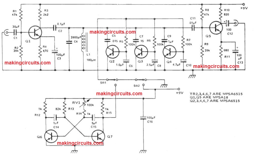
L and C4 work like a band pass filter along with resonant frequency equivalent to
f = 1 / 2π√L.C4
Along with the values displayed in this article this value is around 6kHz. The R-C networks R5-C6 R6-C8 R7-C10 work as time intervals to turn on Q2,3,4 correspondingly in sequence pursuing the closing of SW2.
This switches C5, C7, C9 along the filter in turn, pulling the resonance point across the audio band.
The time constants are in such a way that the sequence of switch on is Q2, Q3 and Q4.
This resonance varies from 6kHz-2k7Hz-950Hz--to 400Hz when Q4 turn on. When the switch is released the electrolytics discharge with the 100k resistors to ground, turning off the transistors.
Automatic switching is supplied by the multivibrator, the frequency of which is placed by RV1.
Once the 'auto' switch SW1 is closed a slow square wave of around 8V is placed on the charging resistors.
Therefore the transistors are pulsed ON / OFF. C13 is to decouple the supply to the oscillator to avoid issues with fluctuations as the oscillator switches state.
Thanks for the op-amp circuit. I intend to have a go building this for myself.
However it’s missing very important information as there’s no power supply definitions.
Would I be correct in assuming the TLO84’s and LM3080’s (or CA3080) require a split rail supply?
In the range of +/- 12 to 15V?…
The 3080 datasheet would suggest this as there in no mention of single supply implementation.
Many thanks,
Alex.
Split supply is not required. It can work with a single 12V power supply
Just for clarification, what do U and UC refer to? I’m assuming U is 12V in but as I’m looking at it there would be a short to 0V when the VR1 is fully open.
UC is the control voltage between 0V and 12V derived from the swell pedal. I can’t figure out the exact functioning of the circuit since it is a guitar specific circuit and I have no knowledge about electric guitars. The low current control voltage UC can be connected to ground through P1 I guess, this is evident as far the circuit around P1 is concerned.
Thanks for all your details to the nuances
Thank you!