In this post we learn how to test a SCR whether it's good or bad using a couple of simple circuit implementations
Simple SCR testing circuit
Referring to the diagram below initializing the shown normally-open “on” push to ON button connects the gate to the anode, enabling current coming from the negative lead of the battery, by means of the cathode-gate PN junction, via the switch, by way of the load resistor, and returning to the battery. This specific gate current must compel the SCR to latch on, permitting current to move straight through cathode to anode without additionally activating via the gate. While the “on” pushbutton is removed, the load needs to continue to be switched ON.
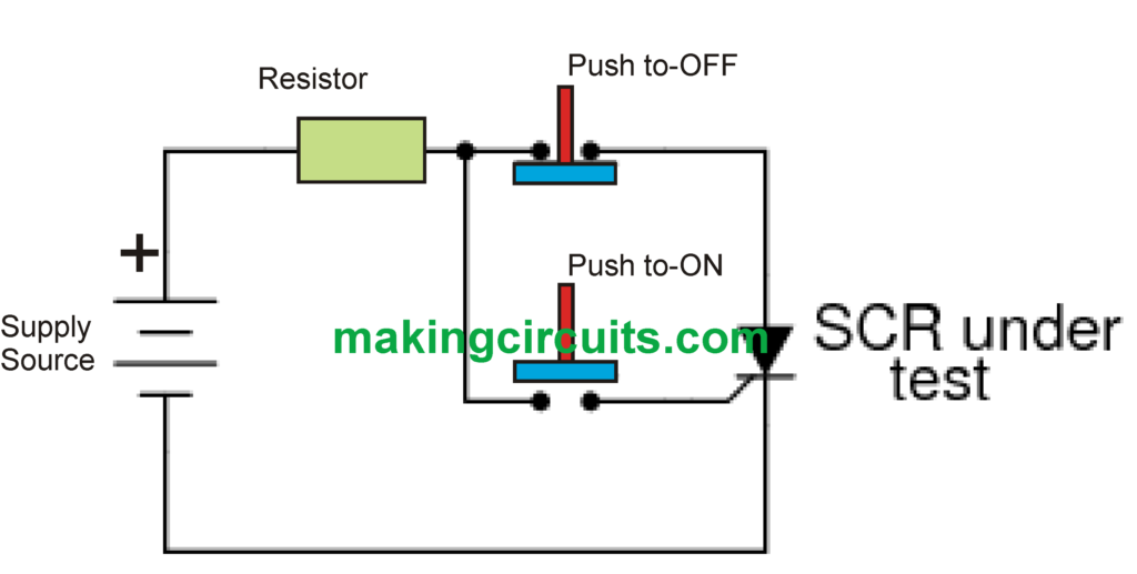
Pressing the normally-closed “off” push-button switch switches OFF the circuit, driving current via the SCR to end, consequently purging it to deactivate (low-current dropout).
When the SCR is unable to latch, the issue could be with the connected load rather than the SCR. Some nominal level of load current needs to maintain the SCR latched in the “on” condition. This lowest possible current quantity is named the holding current. A load with exceedingly high a resistance usually will not get adequate current to maintain an SCR latched while gate current ends, as a result delivering the erroneous appearance of a poor (unlatchable) SCR in the evaluation circuit. Retaining current values for various SCRs ought to be provided by the manufacturing companies. Average retaining current magnitudes range between 1 milliamp to 50 milliamps or even more for more substantial models.
For the evaluation to be completely exhaustive, above the activating action is required to be examined. The forward breakover voltage constraint of the SCR could possibly be analyzed by maximizing the DC voltage supply (without having pushbuttons actuated) until the SCR latches pretty much all by itself. Be careful that a breakover check might need greatly increased voltage: numerous power SCRs possess break down voltage ratings of 600 volts or higher! Additionally, in case a pulse voltage generator can be obtained, the crucial rate of voltage surge for the SCR could possibly be examined in the same manner: confront it to oscillating supply voltages of unusual V/time rates without pushbutton buttons actuated and observe where it latches.
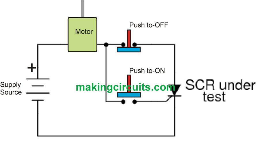
In this particular straightforward structure, the SCR test circuit could possibly be sufficient as a start/stop control circuit for a DC motor, lamp, or other functional load: (Figure below)
DC Motor start and stop controller circuit using an SCR
A different functional SCR test circuit implementation for the SCR in a DC circuit is often as a crowbar unit for over-voltage protection. A “crowbar” circuit includes an SCR positioned in parallel with the output of a DC power source, for positioning an immediate short-circuit on the output of the particular supply to protect against extreme voltage from arriving at the load. Harm to the SCR and power supply is eliminated by the cautious positioning of a fuse or tangible series resistance prior to the SCR to minimize short-circuit current: (Figure below)

Leave a Reply