An electronic circuit built using four diodes that converts an AC input to a DC output is called a bridge rectifier. We refer to this procedure as a full wave rectification.
In this lesson, we cover the fundamentals of rectifier diodes, such 1N4007 or 1N5408, and how you can connect them to create a bridge rectifier circuit efficiently.
Overview
Diodes play a crucial role as electronic parts in converting AC to DC. Diodes can conduct DC in one direction and convert AC to DC across their terminals. Let's delve deeper into the components.
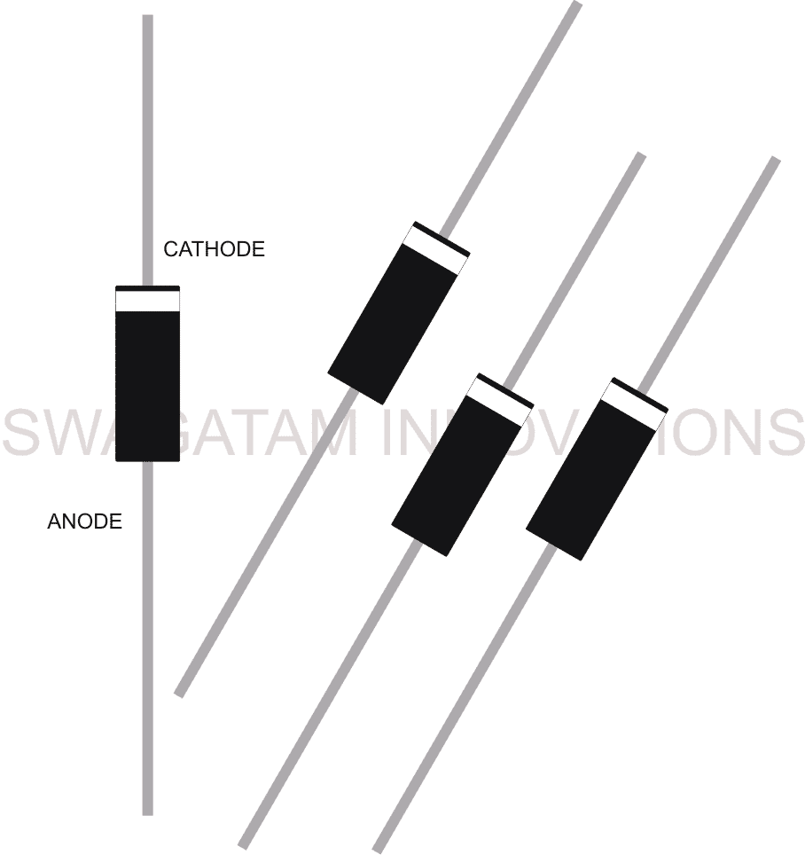
Diodes are small electronic parts that are typically distinguished by their cylindrical black body with a white band at one end.
How to Understand Pinouts of a Rectifier Diode
Their body has two pins located on opposite ends.
The leads, also known as pins, are designated with correct polarities known as the cathode and anode.
The cathode is located at the end with bands, while the anode is at the opposite end.
Typically the black diodes have a higher amp rating compared to the smaller red diodes which have a lower power rating.
The power rating indicates the amount of current the device can handle without causing it to reach damaging temperatures.
Diodes possess a single crucial role that defines their uniqueness. When an AC is passed through a diode from the anode to the ground, it produces a DC output from the cathode to the ground converting the AC to DC through rectification.
How is Rectification achieved in diodes?
An alternating current consists of fluctuating voltage levels, continuously switching polarity from zero to peak voltage, back to zero, then to the opposite polarity and downward to the negative peak before returning to zero to start the cycle again.
The alternating shifts in polarity, or cycles, may vary in duration based on the AC frequency or vice versa.
When the AC power is applied to the anode of a diode compared to ground, the diode blocks the negative cycles and only allows the positive cycles to flow through to the cathode relative to ground.
If an identical AC signal is used across the diode's cathode compared to ground, the positive cycles are restricted, allowing only the negative cycles to be received in relation to ground.
Depending on the diodes polarity, the AC input is rectified so that only a certain voltage is present at the device's output.
When it is necessary to utilize both cycles of an AC to improve efficiency and obtain a fully rectified AC, a bridge rectifier is utilized.
A clever setup of four diodes in a bridge rectifier configuration ensures that both halves of the applied AC cycle are rectified.
Both the positive and negative cycles are transformed into positive potentials at the bridge configuration output. This configuration leads to an improved and more effective AC signal.
A filter capacitor is typically placed at the end of a bridge to help compensate for any voltage irregularities or sudden blackouts by utilizing the stored charge to produce a more stable and smoother DC output.
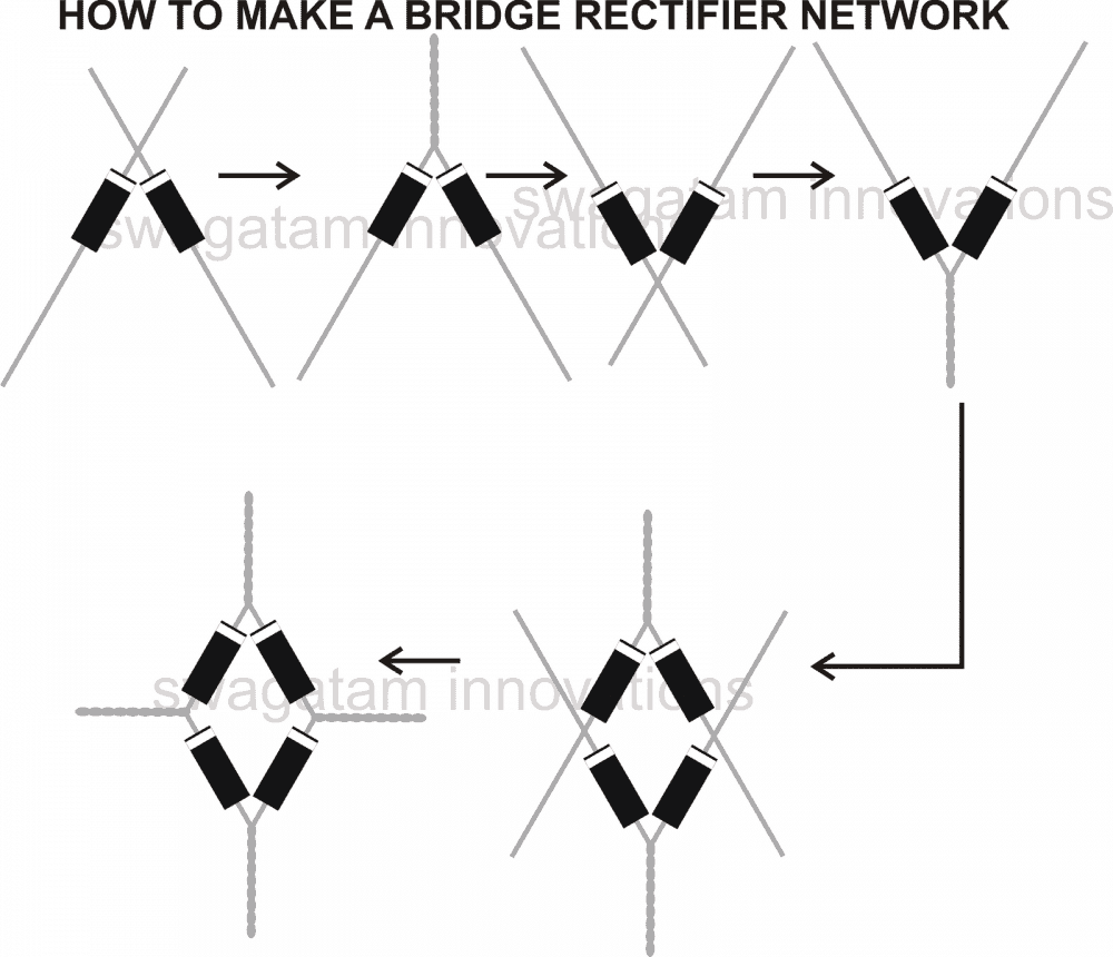
Guide on creating a bridge rectifier circuit with 1N4007 diodes
Creating a bridge rectifier with four 1N4007 diodes is not a challenging undertaking. By turning the terminals of the four diodes in a particular way, a bridge rectifier can be created quickly.
These steps can be used to create a bridge rectifier:
Use four 1N4007 diodes.
Select two of them and line up their bound edges or the negative ends so that they form an arrow-like configuration.
Twist the terminals securely to maintain the orientation of the joint. Set aside this connected pair of diodes.
Next select the final pair of diodes and perform the same process as before, ensuring that this time the opposite terminals or cathodes, undergo the steps outlined above.
At last, the last step is to connect the ultimate bridge network by linking the previously mentioned two assemblies together with their corresponding loose ends as illustrated in the diagram.
Your bridge rectifier design is complete and suitable for the intended purpose.
Alternatively the above explained method of making a bridge can be followed over a PCB also by inserting the diodes in the PCB as per the explained orientations and by soldering them at the required places.
Leave a Reply