• Skip to main content
  • Skip to primary sidebar

Making Easy Circuits

Learn and build electronic circuits

You are here: Home / Water Sensor and Controller / IC 555 Dry Run Protection Circuit

IC 555 Dry Run Protection Circuit

Last Updated on December 29, 2024 by Admin Leave a Comment

An preexisting circuit for an IC 555-based water level controller may be modified to include the dry run protection, as seen below:

IC 555 Dry Run Protection Circuit

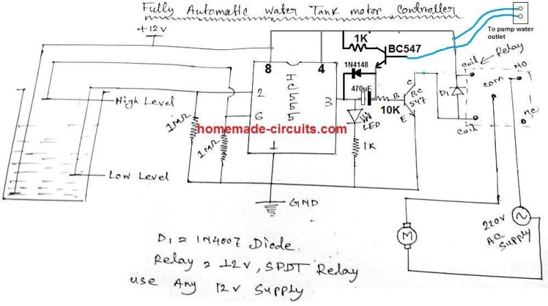
In the schematic above, the dry run function operates as follows:

The IC's pin #2 loses its positive voltage whenever the water level falls beneath the "low level" probe. As a result, pin #2 becomes low, which immediately raises pi #3.

The pump motor is turned on when this strong signal crosses the 470uF capacitor, which turns on the relay driver stage.

Only until the 470 uF charges—which could take three to five seconds—do the relay driver and pump stay turned on.

Should the pumps begin to pull water during this period, the pumped water might be able to cross the water sensor that is attached to the blue wires.

Bypassing the 470 uF capacitor, this corresponding BC547 will have obtained the base bias and start conducting. Up until the full tank level is attained, this threshold will allow the relay driver BC547 to operate freely.

However, in the case that there is no water and the pump goes dry, the top BC547 cannot be biased, and finally the 470 uF will be fully charged, preventing any more base current from reaching the relay driver stage. As a result, the relay will be turned off, avoiding the dry run situation.

You'll also like:

  • 1.  ULN2003 Water Level Controller Circuit
  • 2.  Automatic Submersible Pump Controller Circuit with Dry Run Protection
  • 3.  Water Level Controller using a Single SCR
  • 4.  How to Make a Light Activated Water Level Controller Circuit
  • 5.  Water Level Controller Circuit using only Transistors
  • 6.  Anti Corrossive Water Level Probe Circuit

About Admin

Hey friends, Thanks a bunch for stopping by this site! I am an engineer with a Bachelor of Engineering in Electronics and Telecommunication. One of my passions is gathering information from all sorts of electronics books and tutorials. I then take that information and compile it into a language that is super easy to understand. My goal is to make those complex electronics circuit concepts and technical terms much more accessible for all the new and budding electronics engineers out there. I can also design customized circuit diagrams as required by the users.
If you have any questions related to this field, please do not hesitate to drop a comment! I am always here and ready to help you out with any queries you might have. I cannot wait to hear from you!

Reader Interactions

Leave a Reply Cancel reply

Your email address will not be published. Required fields are marked *

Primary Sidebar

Categories

  • 3 Phase (4)
  • 8051 Microcontroller (1)
  • Arduino (11)
  • Audio and Amplifier (102)
  • Automation (8)
  • Battery Chargers (64)
  • Bicycle Projects (4)
  • Car and Motorcycle Projects (39)
  • Datasheets (10)
  • DIY Projects (5)
  • Electrical (15)
  • Free Energy (6)
  • Games Projects (2)
  • High Voltage (14)
  • Hobby Projects (30)
  • Household Circuits (2)
  • IC 555 Circuits (5)
  • Ignition Circuits (2)
  • Indicators (50)
  • Infrared (6)
  • Inverter Circuits (29)
  • Lights and Lamps (97)
  • Medical (8)
  • Meter and Tester Circuits (38)
  • Motor Driver (17)
  • New Circuits (56)
  • Oscillators (30)
  • Pets and Pests (5)
  • Power supply (80)
  • Protection Circuits (25)
  • PWM (9)
  • Remote Control (20)
  • Security and Alarm Circuit (48)
  • Sensors and Detectors (66)
  • Signal Processor (23)
  • Solar Controller Circuits (62)
  • SSR (3)
  • Temperature Controller (20)
  • Timer (25)
  • Transformerless (7)
  • Transmitters (12)
  • Tutorials (45)
  • UPS (2)
  • Voltage Regulators (57)
  • Water Sensor and Controller (29)
  • Home
  • Privacy Policy
  • Contact
  • Disclaimer
  • Copyright

© 2025 · Making Easy Circuits