Elegant and intriguing light displays may be produced with common ICs like the IC 4017 and IC 555, as seen below, even if more intricate lighting may need the use of microcontroller ICs.
This is our initial design for an LED chaser that just needs a few parts to be put together.
(Any required chasing speed or rate may be achieved by adjusting the 100K pot.)

Parts List
| Category | Description | Quantity |
|---|---|---|
| Resistors | 1K | 11 nos |
| 10K | 2 nos | |
| 100K Pot | 1 no | |
| Capacitors | 0.01uF Ceramic Disc | - |
| 10uF/25V Electrolytic | - | |
| Semiconductors | LEDs RED, 5mm High Bright or as desired | 11 nos |
| IC 4017 | 1 no | |
| IC 555 | 1 no |
Note: All resistors are 1/4 watt, 5% unless specified.
This design shows how the IC 4017 creates a running or chasing light sequence throughout the 10 output LEDs that are connected according to the pulses from the IC 555. for as long as the IC 555 continues to pulse pin #14 of the IC 4017, the chasing sequence will keep on reproducing itself from beginning to end.
How to Determine the Speed of the Chaser
As I've described below, figuring out the IC 555's proper frequency rate makes it simple to modify the chaser speed:
TL = 0.693 x R2 x C (TL refers to time LOW or the OFF time of the frequency)
TH = 0.693 x (R1 + R2) x C (TH refers to time HIGH or the ON time of the frequency)
D = Duty Cycle= (R1 + R2) / (R1 + 2R2)
Or,
R1 = 1.44 x (2 x D-1) / (F x C)
R2 = 1.44 x (1 - D) / (F x C)
Although it may be adjusted to work with mains-operated bulbs as well, the majority of the lights attached are LEDs.
Even though the layout described above is fantastic, with a few small adjustments as shown below the identical IC 4017 and IC 555 combo may be used to produce far more intricate and captivating light effects:
IC 4017 LED Knight Rider Chaser Circuit
So here is the second circuit we are looking at. It is essentially a running light effect generator, think of it like the "Knight Rider" car lights, you know that cool scanning light thing? Yeah it is pretty much trying to mimic that….
The main players here are the IC 555 and the IC 4017. We are using the IC 555 to pump out clock pulses which then get fed into the IC 4017's clock input.
Parts List
| Part | Quantity |
|---|---|
| 1K Resistor | 1 |
| 22K Resistor | 1 |
| 1M Resistor | 1 |
| 10 ohms Resistor | 1 |
| 500K Potentiometer | 1 |
| 1uF/25V Capacitor | 1 |
| 1000uF/25V Capacitor | 1 |
| 0.47uF/400V PPC | 1 |
| 12V Zener Diode (1W) | 1 |
| 1N4007 Diodes | 4 |
| 1N4148 Diode | 10 |
| LEDs | 6 |
| IC 4017 | 1 |
| IC 555 | 1 |
Basically these clock pulses from the IC555 get translated into a cool sequencing or chasing effect on the LEDs that are hooked up to the various outputs of the IC 4017.
Now normally the IC 4017 would just light up the LEDs one after the other, start to finish, in a simple sequence. The speed of this sequence would depend on the IC 555's clock frequency and it would just keep repeating as long as we keep the power on.
But for this "Knight Rider" effect we have wired up the IC 4017's output in a special way using some diodes. This little trick makes the LEDs chase back and forth instead of just going in one direction. We are only using 6 LEDs for this though unlike the normal 10 you would get in a standard setup.
How It All Comes Together
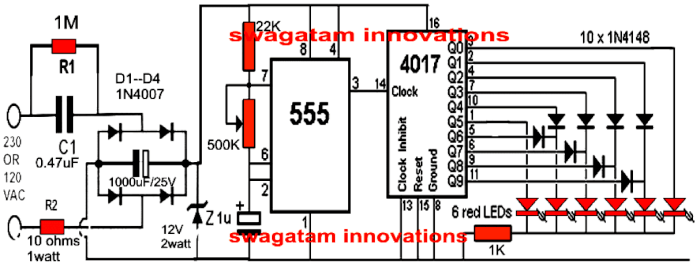
If you peep at the first circuit diagram then you will see that we are getting that reverse-forward moving effect on the LEDs thanks to the clock pulses from the IC 555, which is set up as an astable multivibrator.
And here is a fun part, you can tweak the speed of the LED sequence by playing around with the 500k pot connected to the IC 555 because that will change the frequency of the astable multivibrator.
To power the whole thing we are using a nifty little transformerless power supply circuit. This saves us from having to use big, clunky transformers or expensive SMPS units.
Amping It Up
Now if you are feeling adventurous then you can even modify this circuit to light up regular mains-operated bulbs! All you have got to do is throw in a few triacs along with the LEDs at the outputs.
The second figure below shows how to do this. We have got 6 triacs wired up to the output LED ends with 1 K resistors.
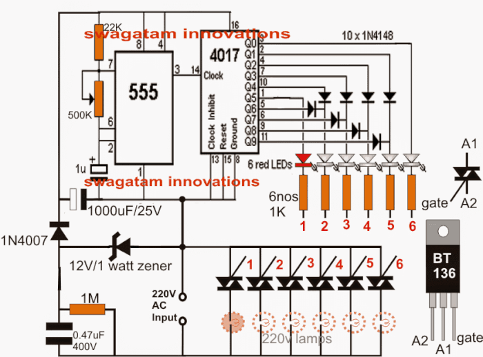
And guess what? This mains-operated "Knight Rider" light chaser still rocks that simple capacitive power supply so we are still avoiding those bulky power supplies while getting that awesome running light effect.
WARNING: SERIOUSLY, BE CAREFUL! This circuit is directly connected to the mains AC supply which means it is super dangerous to touch when it is powered up and uncovered! You could get a nasty shock, so please be extra cautious!
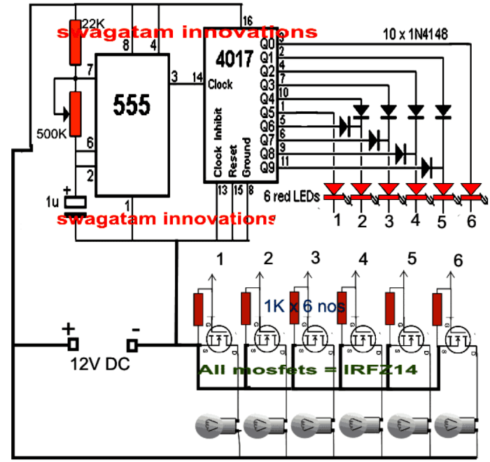
Another IC 555/ IC 4017 Knight Rider Chaser Circuit with 12V Bulbs
By making the following adjustments, the aforementioned circuit may be utilized for automobile installation just as well. The circuit demonstrates how the design may be applied to 12V automobile lighting.
Leave a Reply